
Adjustable locking windage and elevation knob
a technology of locking windage and elevation knob, which is applied in the direction of mechanical control devices, instruments, process and machine control, etc., can solve the problems of assembly being easily knocked out of position, the illumination reticle to turn off or the scope to become unfocused at an inopportune time, and the time and inconvenience of having to remove the dust cap, etc., to achieve the effect of simple formation
Patent Information
- Authority / Receiving Office
- US · United States
- Patent Type
- Applications(United States)
- Current Assignee / Owner
- Publication Date
- 2006-12-14
Smart Images
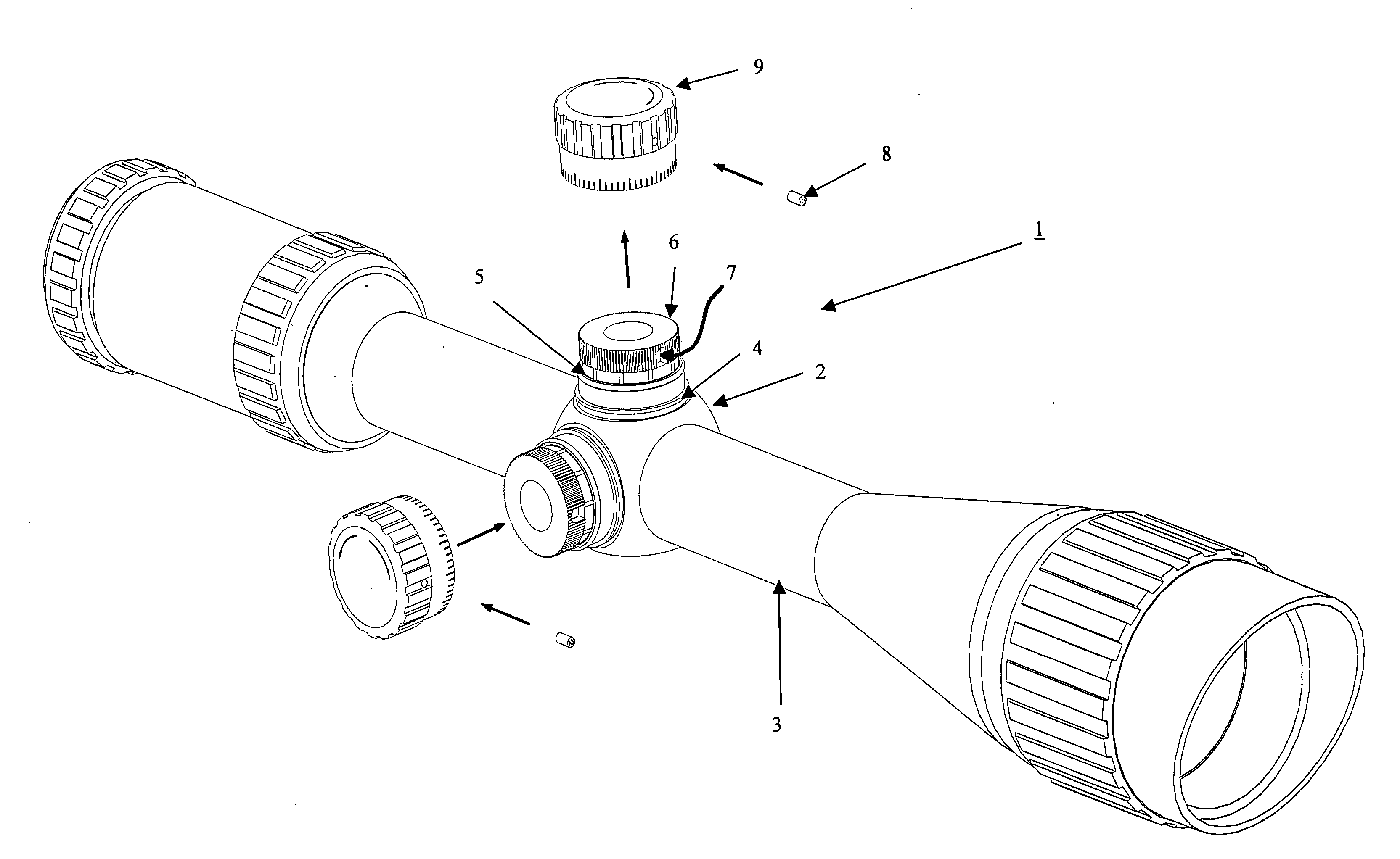
Figure 1 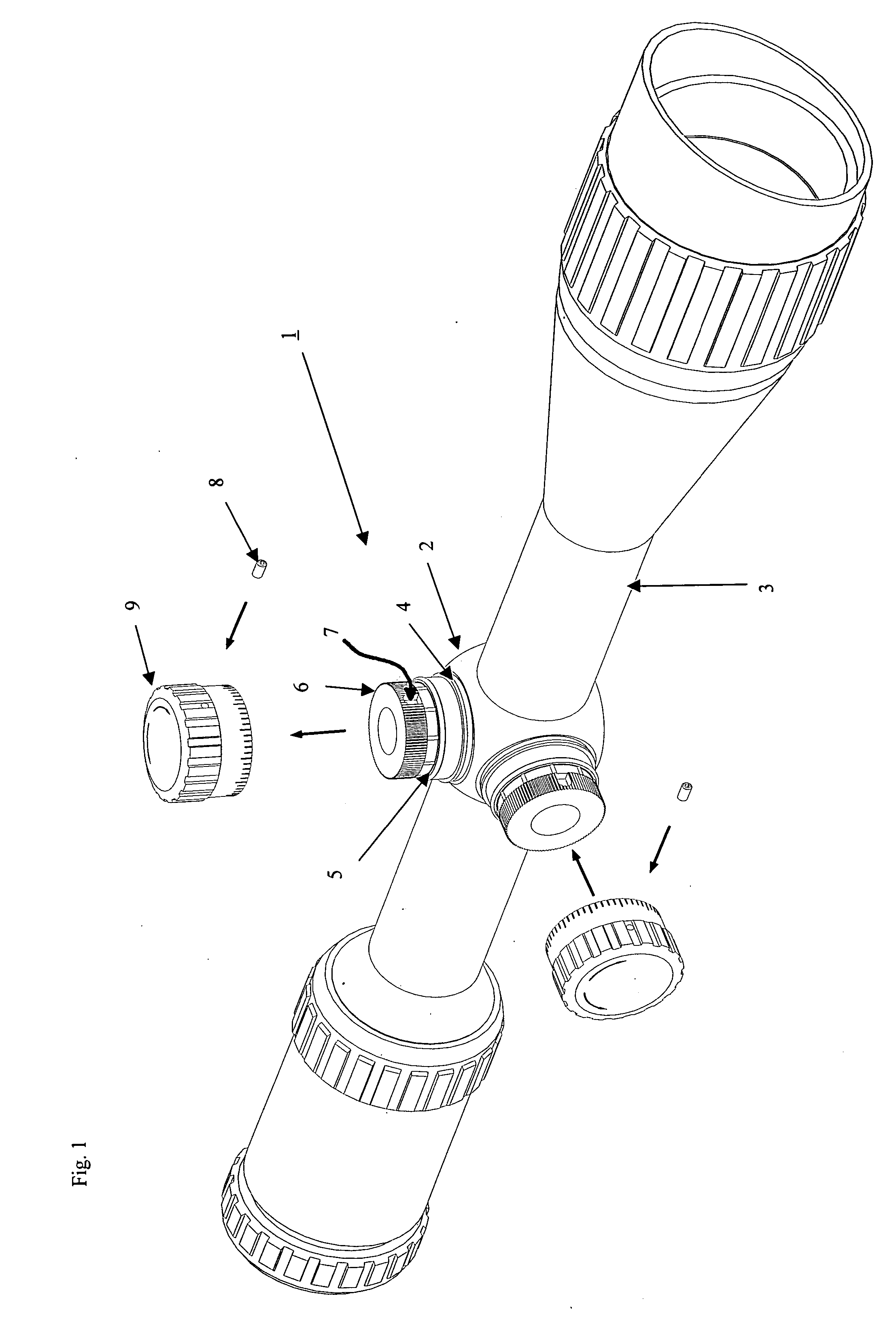
Figure 2 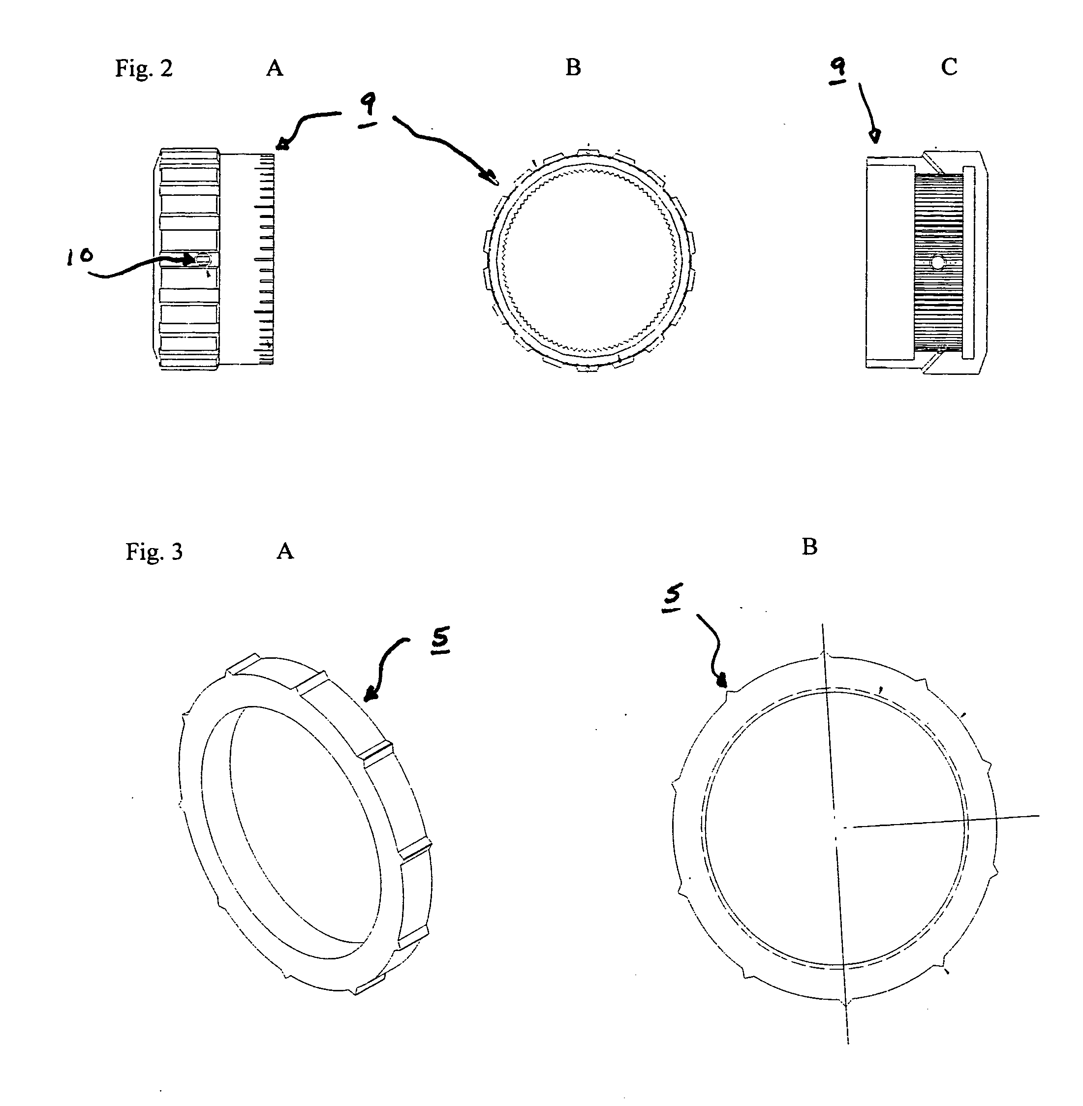
Figure 3
Abstract
Description
FIELD OF THE INVENTION
[0001] This invention relates to the design and construction of a novel, adjustable locking windage and elevation knob assembly for the improved accuracy of scopes. BACKGROUND OF THE INVENTION
[0002] Scopes, particularly those used for hunting, are well known in the prior art. Scopes are generally used to assist hunters in aiming at desired targets. However, because gravity and wind play a role in the trajectory of a bullet by causing the bullet to drop and / or drift to one side of the intended target, hunters have to make adjustments to the scope to account for these effects. Moreover, as the effect of gravity and wind drift on a bullet's trajectory will vary depending upon the distance to the target, multiple adjustments may be necessary at a shooting range or in the field to account for these variances.
[0003] To address the above and other related scope adjustment and performance issues, the prior art has developed to include various adjustment knob assembl...
Examples
Embodiment Construction
[0015] Shown in FIG. 1 is the adjustment knob assembly (1) attached to the turret (2) of a scope (3). A rubber washer (4) is placed between the turret (2) and the adjustment knob assembly (1) to create a weatherproof seal between the turret (2) and the adjustment knob assembly (1).
[0016] A knurl knob (6) is placed above the lock down nut (5). The knurl knob (6) has a hollow groove (7) on its side for receiving a pin (8). A turn knob (9) is placed over the knurl knob (6) and lock down nut (5) to form the adjustment knob assembly (1), as shown in the transparent view of FIG. 2C.
[0017] Once the turn knob (9) is placed over the knurl knob (6) and the lock down nut (5), a pin (8) is placed through the turn knob (9) and is received by the hollow groove (7) on the side of the knurl knob (6), which prevents the knurl knob (6) and turn knob (9) from disengaging during the push-pull movement.
[0018] When the turn knob (9) is pushed down over the lock down nut (5), the annular grooves (11) o...