
Quick change device for the oscillating tool of a vibration welding machine
Patent Information
- Authority / Receiving Office
- US · United States
- Current Assignee / Owner
- Publication Date
- 2007-04-19
- Estimated Expiration
- Not applicable · inactive patent
Smart Images
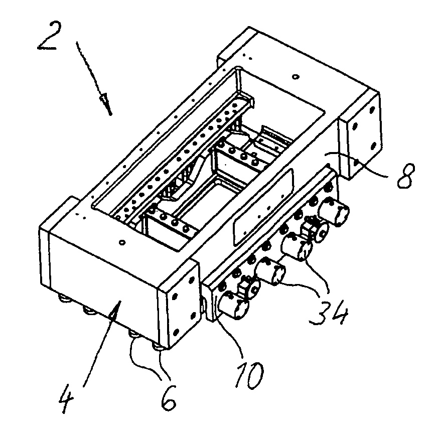
Figure 1 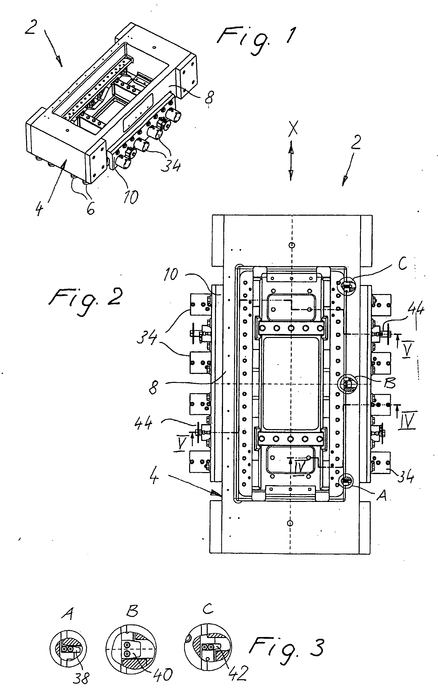
Figure 2 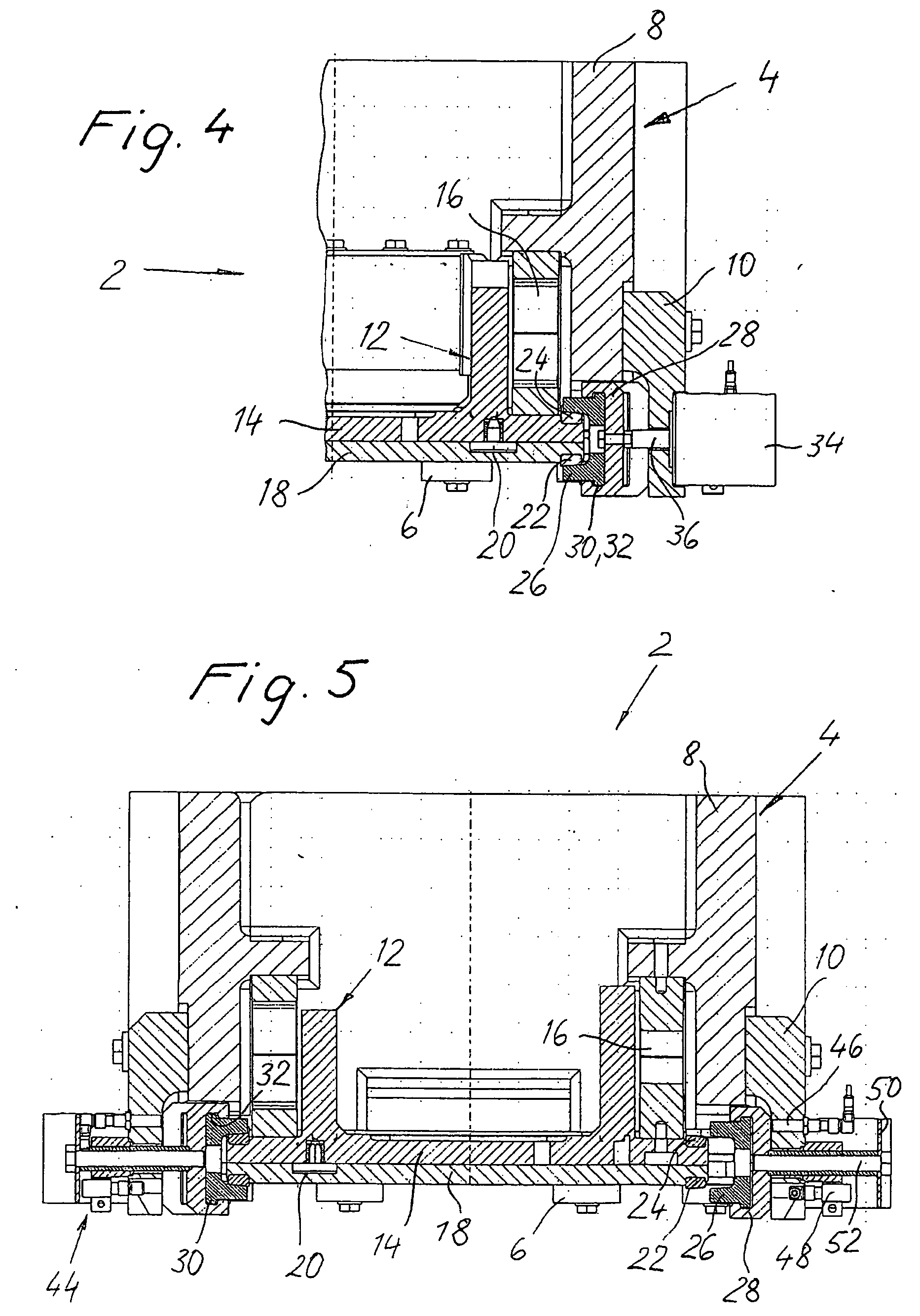
Figure 3
Abstract
Description
BACKGROUND OF THE INVENTION
[0001] The present invention relates to a quick change device for the tool that can be attached to the vibratory unit of a vibration welding machine for receiving a work-piece half to be welded.
[0002] A vibration welding machine has an oscillating tool (upper tool) and a stationary counter piece (bottom tool) for the positive holding of the work-piece halves (plastic parts) to be welded. The change of the work pieces in production (e.g. in the case of a dashboard from left- to right-hand drive) usually also requires the change of the tools, which needs to take place quickly to save time.
[0003] While there are fast and simple change devices for the stationary tool (bottom tool), the change of the oscillating tool usually requires the release of many screw connections. Due to the great dynamic forces affecting the vibratory unit (typical acceleration values during the welding process are 50 to 300 g), the oscillating tool is connected in a force-fit manne...
Examples
Embodiment Construction
[0019] The drawings show an oscillating head 2 of a vibration welding machine (not described in greater detail), wherein the coils of the oscillating head have been omitted in order to simplify the drawing. Since the non-describe part of the vibration welding machine with machine frame, lift table, stationary tool (bottom tool) for receiving the stationary work-piece half, etc. can have a conventional design, it is not described in greater detail here.
[0020] The vibration head 2 has a stationary section in the shape of a bridge 4, which is mounted on the machine frame (not shown) via dampers 6. The bridge 4 is made up of a substantially rectangular frame part 8, to both sides of which are attached longitudinally running, bar-shaped frame parts 10.
[0021] The vibration head 2 comprises an oscillating section in the form of a vibratory unit 12, which includes a vibratory plate 14. The vibratory unit 12 and thus the vibratory plate 14 are suspended from the bridge 4 via leaf springs 1...