
Optical disc apparatus and information recording and reproducing method
a technology of optical discs and information, applied in the field of optical disc apparatuses, can solve the problems of increasing recording time, difficult for this technology to predict a servo signal distortion, increasing recording time, etc., and achieves the effect of reducing recording speed, recording time, and reducing recording speed
Patent Information
- Authority / Receiving Office
- US · United States
- Patent Type
- Applications(United States)
- Current Assignee / Owner
- Publication Date
- 2007-05-31
- Estimated Expiration
- Not applicable · inactive patent
Smart Images
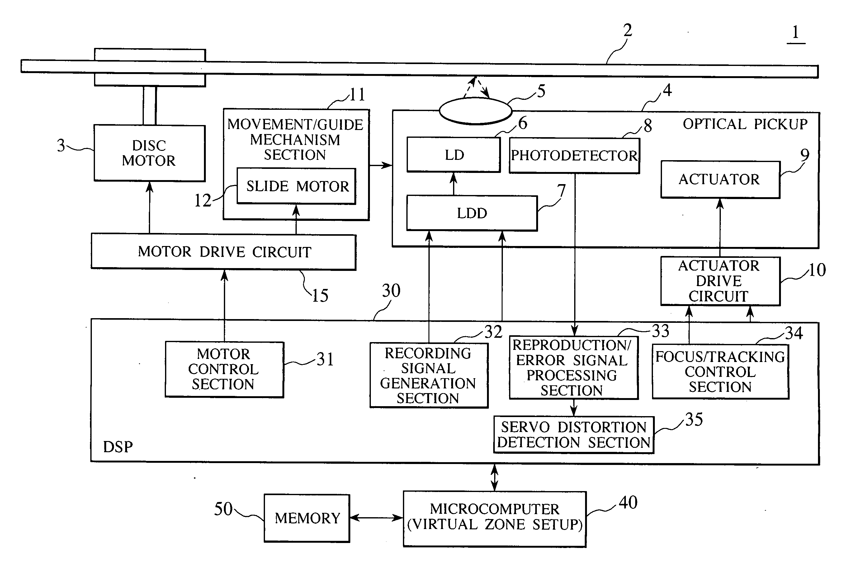
Figure 1 
Figure 2 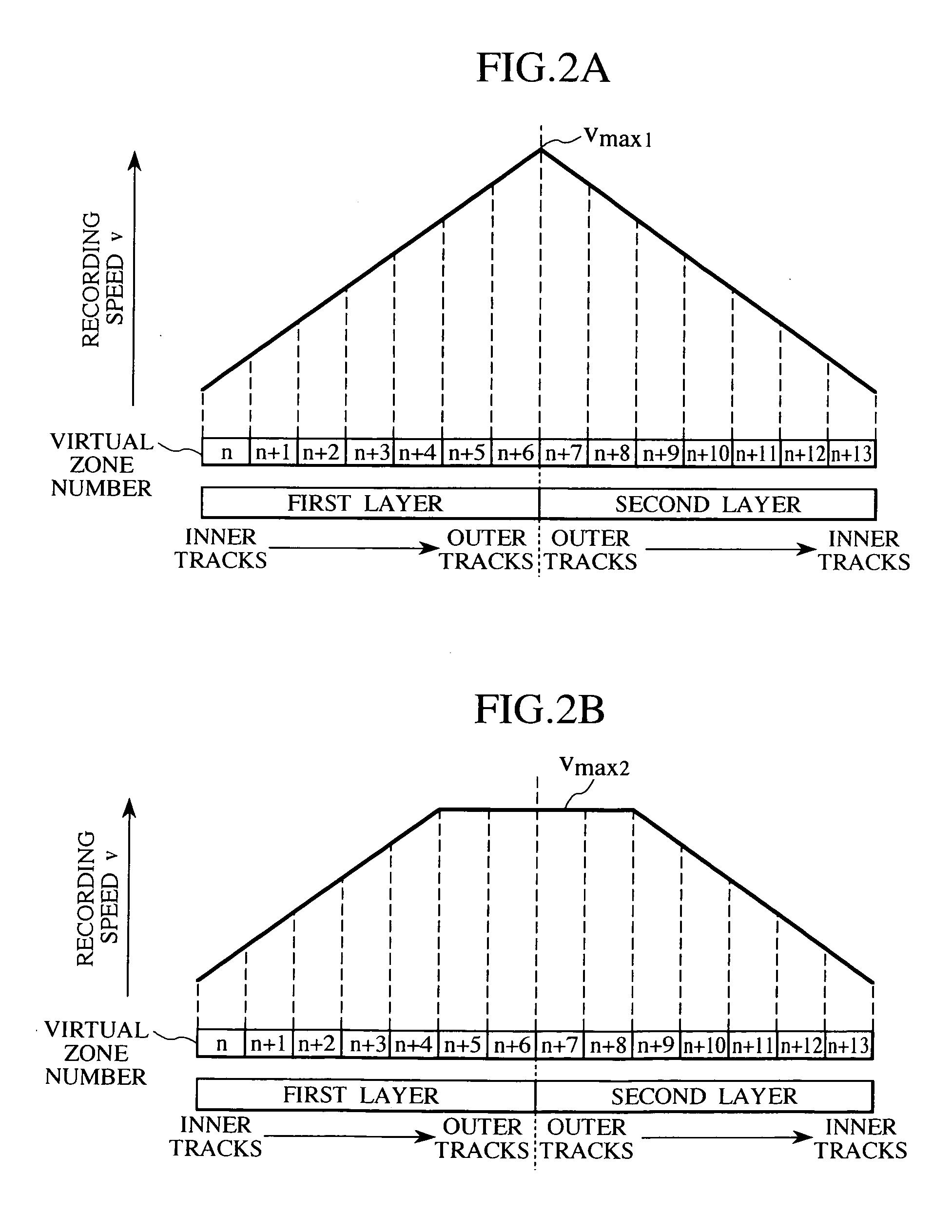
Figure 3
Abstract
Description
CLAIM OF PRIORITY
[0001] The present application claims priority from Japanese application serial No. P2005-341691, filed on Nov. 28, 2005, the content of which is hereby incorporated by reference into this application. BACKGROUND OF THE INVENTION
[0002] 1. Technical Field of the Invention
[0003] The present invention relates to an optical disc apparatus, and more particularly to a technology for recording information onto and reproducing information from a plurality of recording layers on an optical disc.
[0004] 2. Description of the Related Art
[0005] There is a strong market need for increasing the recording speed, that is, reducing the recording time, of DVD±R discs and other optical discs having two recording layers. Conventionally, such a market need has been satisfied by increasing the rotation speed of an optical disc. However, when the rotation speed is increased, the focus servo and tracking servo become unstable due to the distortion possessed by the optical disc, thereby...
Examples
Embodiment Construction
[0025] An embodiment of the present invention will now be described with reference to the accompanying drawings.
[0026] FIGS. 1 to 10 illustrate an embodiment of the present invention. FIG. 1 illustrates a configuration of an optical disc apparatus according to the embodiment of the present invention. FIGS. 2A and 2B illustrate virtual zone setup for the optical disc apparatus shown in FIG. 1. FIG. 3 illustrates virtual zones of the optical disc apparatus shown in FIG. 1 and three recording speed settings (v1, v2, and v3). FIG. 4 shows a first example of recording speed control in the optical disc apparatus shown in FIG. 1. FIG. 5 shows an example of the waveform of a focus servo signal. FIG. 6 illustrates an operation that is performed by the optical disc apparatus shown in FIG. 1. FIG. 7 shows a second example of recording speed control in the optical disc apparatus shown in FIG. 1. FIG. 8 shows a third example of recording speed control in the optical disc apparatus shown in FIG....