
Method and apparatus for automatic gas control for a plasma arc torch
a plasma arc torch and gas control technology, applied in plasma welding apparatus, plasma technique, manufacturing tools, etc., can solve the problems of increasing control difficulties, tedious empirical determinations of different torches, and wear of consumable parts, so as to prolong the life of the electrode, increase the cut duration, and increase the ramp down time
Patent Information
- Authority / Receiving Office
- US · United States
- Patent Type
- Applications(United States)
- Current Assignee / Owner
- Publication Date
- 2008-01-10
Smart Images
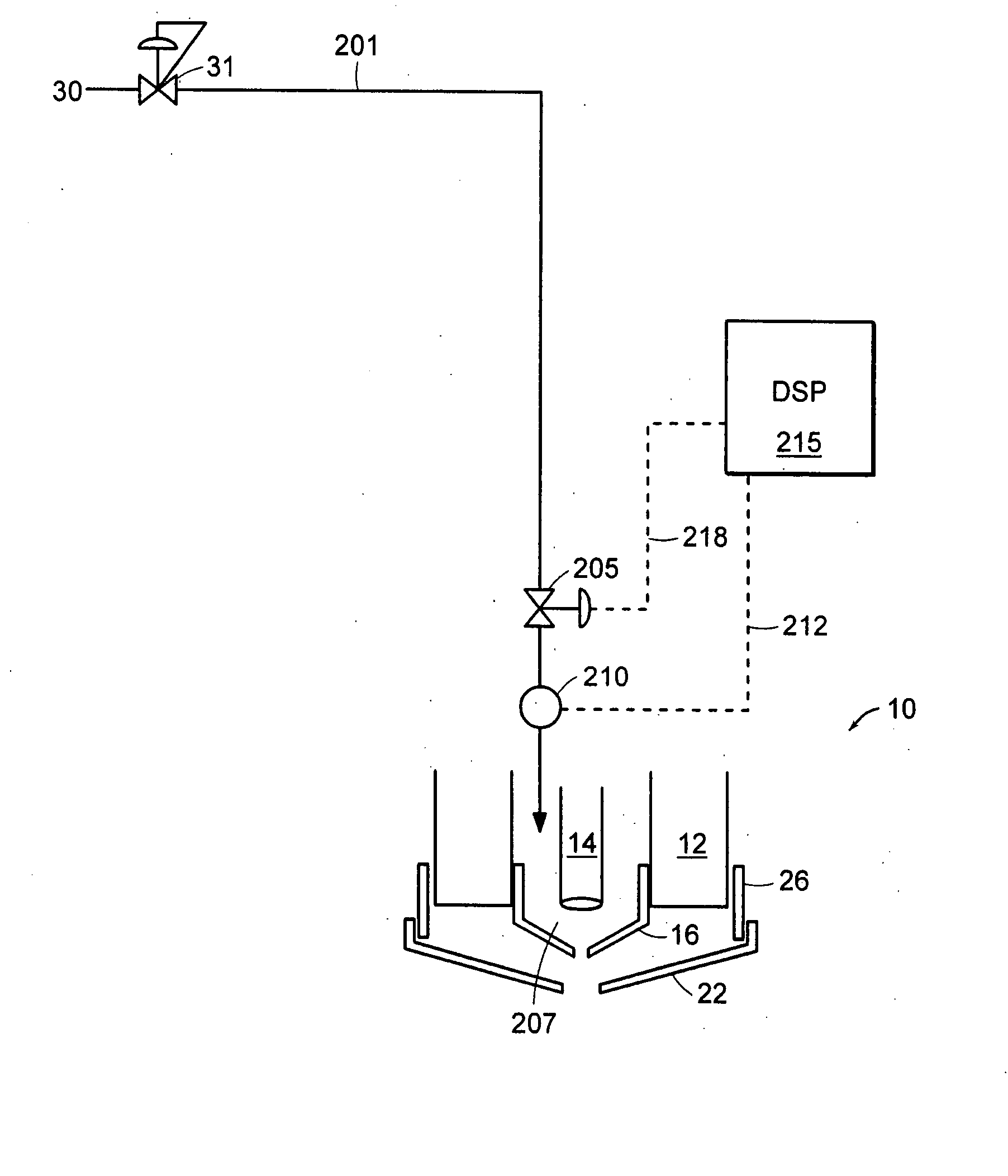
Figure 1 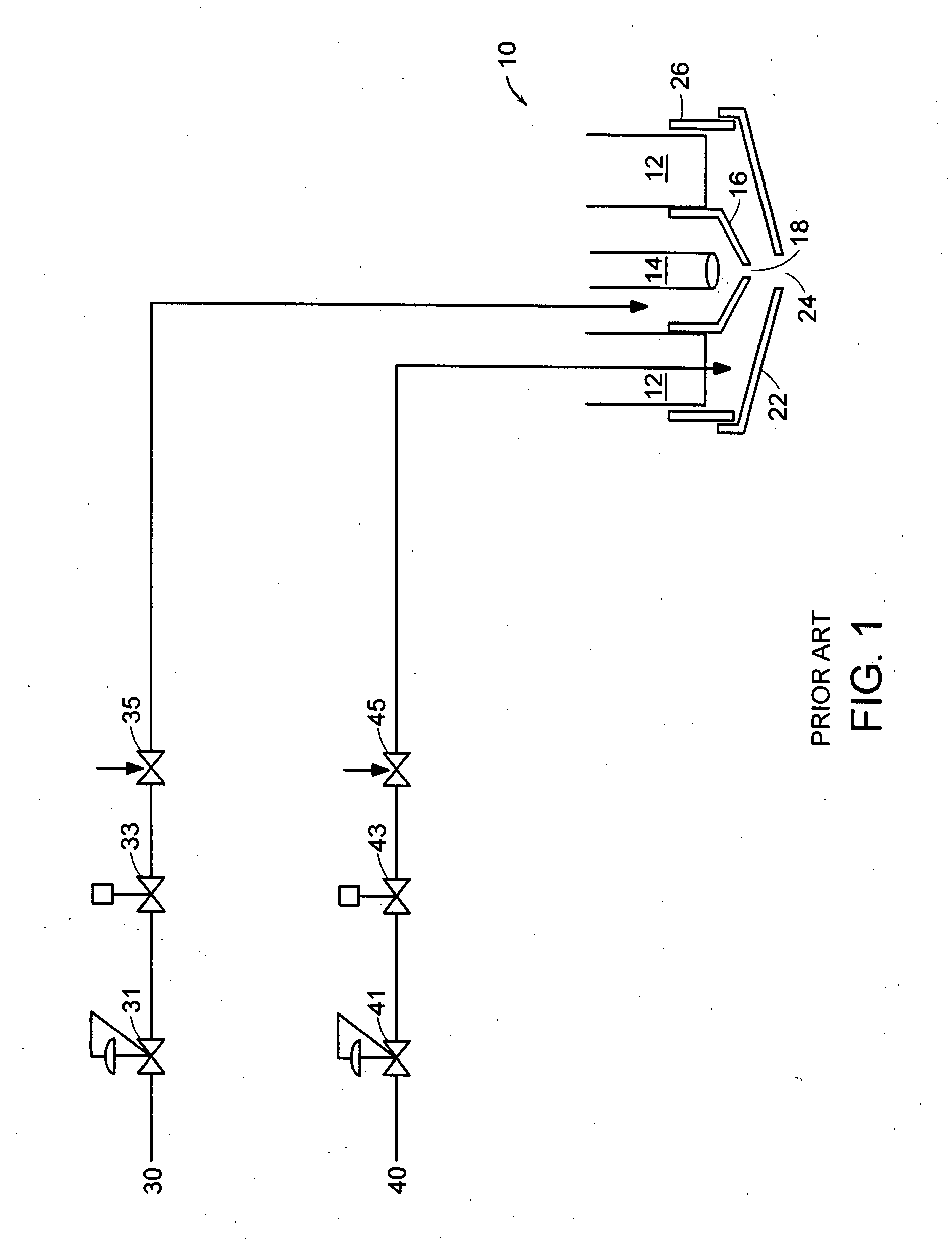
Figure 2 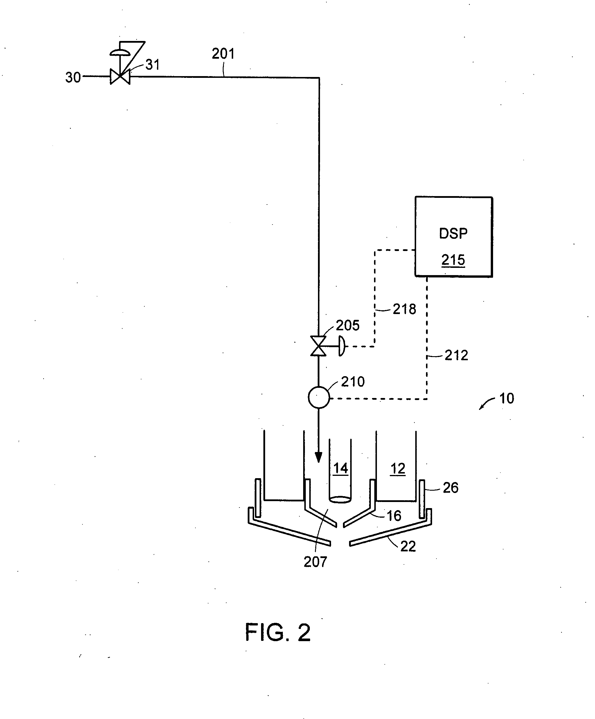
Figure 3
Abstract
Description
RELATED APPLICATIONS
[0001] This application is a continuation-in-part of U.S. Ser. No. 11 / 045,012, filed on Jan. 27, 2005, the contents of which are incorporated herein by reference. This application claims benefit of and priority to U.S. Ser. No. 11 / 045,012.FIELD OF THE INVENTION
[0002] The invention relates generally to plasma arc cutting torches, and more particularly to control systems and methods for controlling gas supplies to such torches to enhance their operation. BACKGROUND OF THE INVENTION
[0003] Plasma arc cutting torches have a wide variety of uses, such as the cutting of aluminum sheet metal, thick plates of steel or stainless steel, or thin sheets of galvanized metal. As illustrated in FIG. 1, a plasma torch 10 includes a torch body 12, an electrode 14 and a nozzle 16 mounted within the body. The nozzle has a central exit orifice 18 and can be surrounded by a shield 22. An exit port 24 of the shield is generally aligned with the exit orifice 18 of the nozzle. A power...
Examples
Embodiment Construction
[0039]FIG. 2 is a schematic representation of a plasma gas supply system to a plasma arc torch incorporating features of the invention. A plasma gas, e.g., including oxygen, nitrogen, and / or argon flows from a plasma gas supply 30 to a plasma gas supply line 201. This first gas supply line channels plasma gas to the plasma torch 10 through a programmable control valve 205 such as a proportional solenoid control valve. The plasma gas flows to a plasma chamber 207 of the torch, and can pass through a sensor 210, such as a flow sensor or a pressure sensor. In some embodiments a signal 212 from the plasma gas sensor 210 can pass to a digital signal processor (DSP) 215 (e.g., a microprocessor, computer, computerized numeric controller (CNC), or PLC), which in turn can manipulate an output 218 to the programmable control valve 205 based on the signal 212. However, the sensor 210 is optional and embodiments include a plasma gas supply line 201 with no sensor 210, and manipulation of the ou...