
Encoder-equipped sealing device
a sealing device and encoder technology, applied in the direction of engine sealing, shaft and bearing components, bearing components, etc., can solve the problems of difficult removal of units, affecting the working efficiency of the fitting device, and the fitting device to become non-operational, so as to achieve the effect of high reliability
Patent Information
- Authority / Receiving Office
- US · United States
- Patent Type
- Applications(United States)
- Current Assignee / Owner
- Publication Date
- 2008-01-24
- Estimated Expiration
- Not applicable · inactive patent
Smart Images
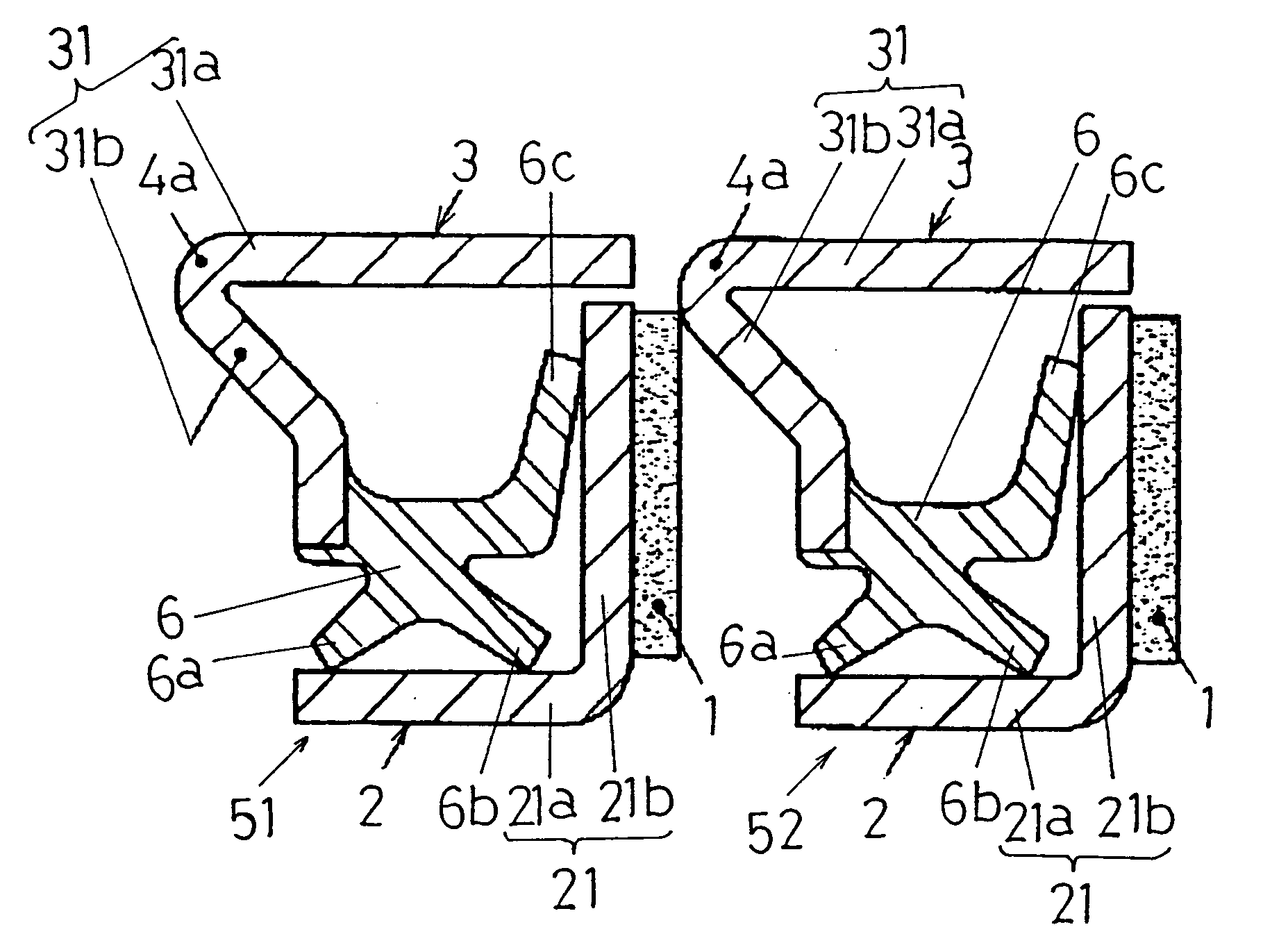
Figure 1 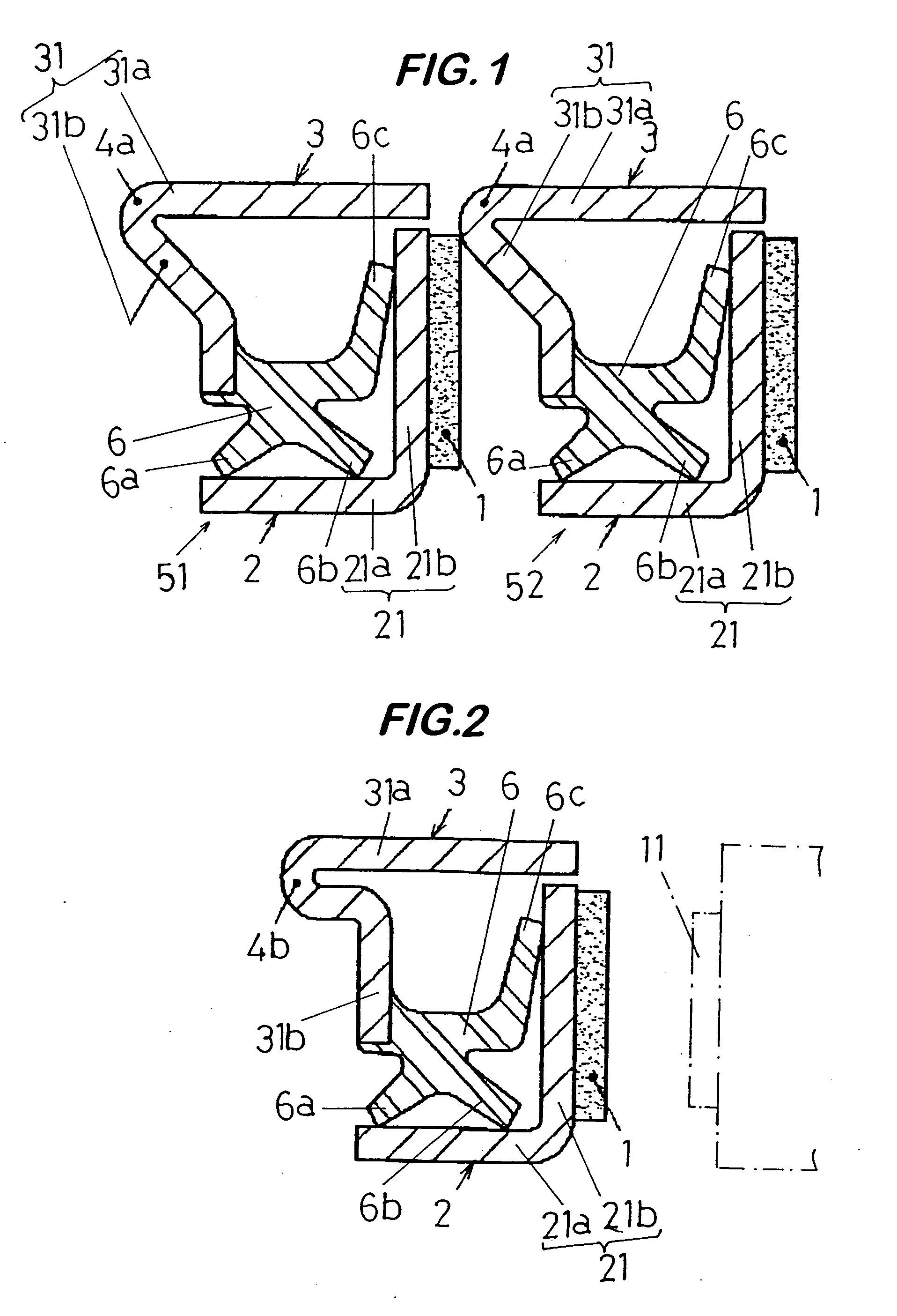
Figure 2 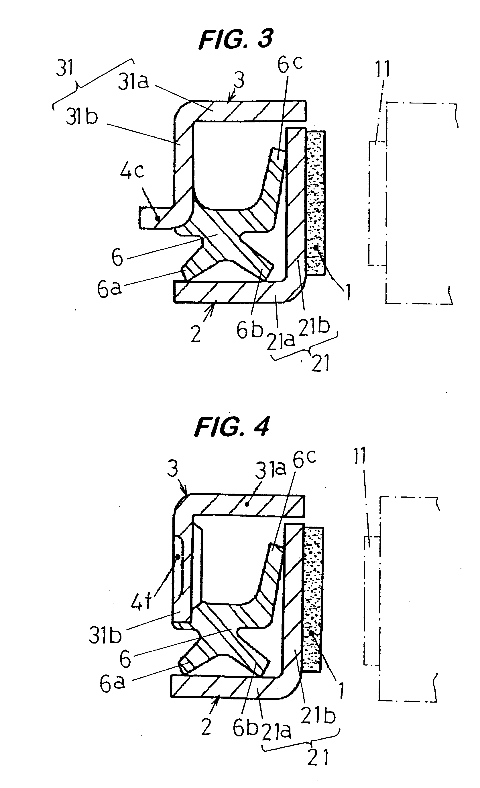
Figure 3
Abstract
Description
[0001] This application is a continuation of U.S. Ser. No. 11 / 500,402, filed Aug. 6, 2006, which is a continuation of U.S. Ser. No. 10 / 690,550, filed Oct. 23, 2003.BACKGROUND
[0002] 1. Field of the Invention
[0003] The present invention relates to an improvement to and / or in an encoder-equipped sealing device or sealing device that has a magnet-based encoder incorporated therein. More particularly, the present invention relates to such encoder-equipped sealing device that provides capabilities for preventing physical cohesion by magnetic attraction from occurring between two or more units of encoder-based sealing devices that are adjacent to each other, when these units are placed one over another so that they are oriented in one particular direction.
[0004] 2. Description of the Prior Art
[0005] An encoder (pulse coder) that is incorporated in the encoder-equipped sealing device that has been described above takes the form of a pulse generator ring that may be mounted on an automot...
Examples
first embodiment
[0049] Referring first to FIG. 1, an encoder-equipped sealing device according to the present invention is described. In encoder-equipped sealing devices 51 and 52, seal element 3 includes a projecting portion 4a on an end of cylindrical portion 31a on a side on which flange portion 31b is located. The projecting portion 4a extends beyond a side of the flange portion 31b opposite a side on which seal portion 6 is located and in a direction in which the cylindrical portion 31a extends. That is to say, the projecting portion 4a extends beyond the left side of the flange portion 31b in FIG. 1.
[0050] In the embodiment shown in FIG. 1, an end of the cylindrical portion 31a that is located on the left side and a base end of the flange portion 31b are formed in such a manner as to extend toward the left side. This before described portion extends toward the left side in FIG. 1 and forms the projecting portion 4a.
[0051] Referring next to FIG. 2, an encoder-equipped sealing device according...
third embodiment
[0053] Referring next to FIG. 3, an encoder-equipped sealing device according to the present invention is described.
[0054] In the encoder-equipped sealing device shown in FIG. 3, seal element 3 includes a projecting portion 4c extending beyond a side of flange portion 31b opposite a side on which seal portion 6 is located and extending in a direction in which cylindrical portion 31a extends. That is to say, the projecting portion 4c extends beyond the left side of the flange portion 31b in FIG. 3.
[0055] In the third embodiment shown in FIG. 3, the projecting portion 4c is formed by bending an end of the flange portion 31b toward the left side in FIG. 3. It should be noted that this embodiment may be varied such that the projecting portion 4c can be located on a middle portion of the flange portion 31b.
fourth embodiment
[0056] Referring next to FIG. 5, an encoder-equipped sealing device according to the present invention is described.
[0057] In the encoder-equipped sealing device shown in FIG. 5, end portion 4d of cylindrical portion 31a of the seal element 3 extending toward another seal element 2 extends in a direction in which the cylindrical portion 31a extends. And, the end portion 4d further extends beyond a side of the other seal element 2 opposite the side on which the other seal element 2 faces opposite the seal element 3. That is to say, the end portion 4d of the cylindrical portion 31a of the seal element 3 extends beyond the right side of the seal element 2 in the direction in which the cylindrical portion 31a extends.
[0058] In the fourth embodiment shown in FIG. 5, an encoder 1 is arranged on a side (right side in FIG. 5) of flange portion 21b opposite a side on which the flange portion 21b faces the seal element 3. Since the end portion 4d of the cylindrical portion 31a of the seal el...