
Expandable reverse shoulder trial
a trial and expansion technology, applied in the field of expandable reverse shoulder trial, can solve the problems of dislocation of joints, decrease in size and cost of overall instrument sets, etc., and achieve the effects of reducing distance, increasing thickness, and facilitating trialing
Patent Information
- Authority / Receiving Office
- US · United States
- Current Assignee / Owner
- Publication Date
- 2009-04-16
Smart Images
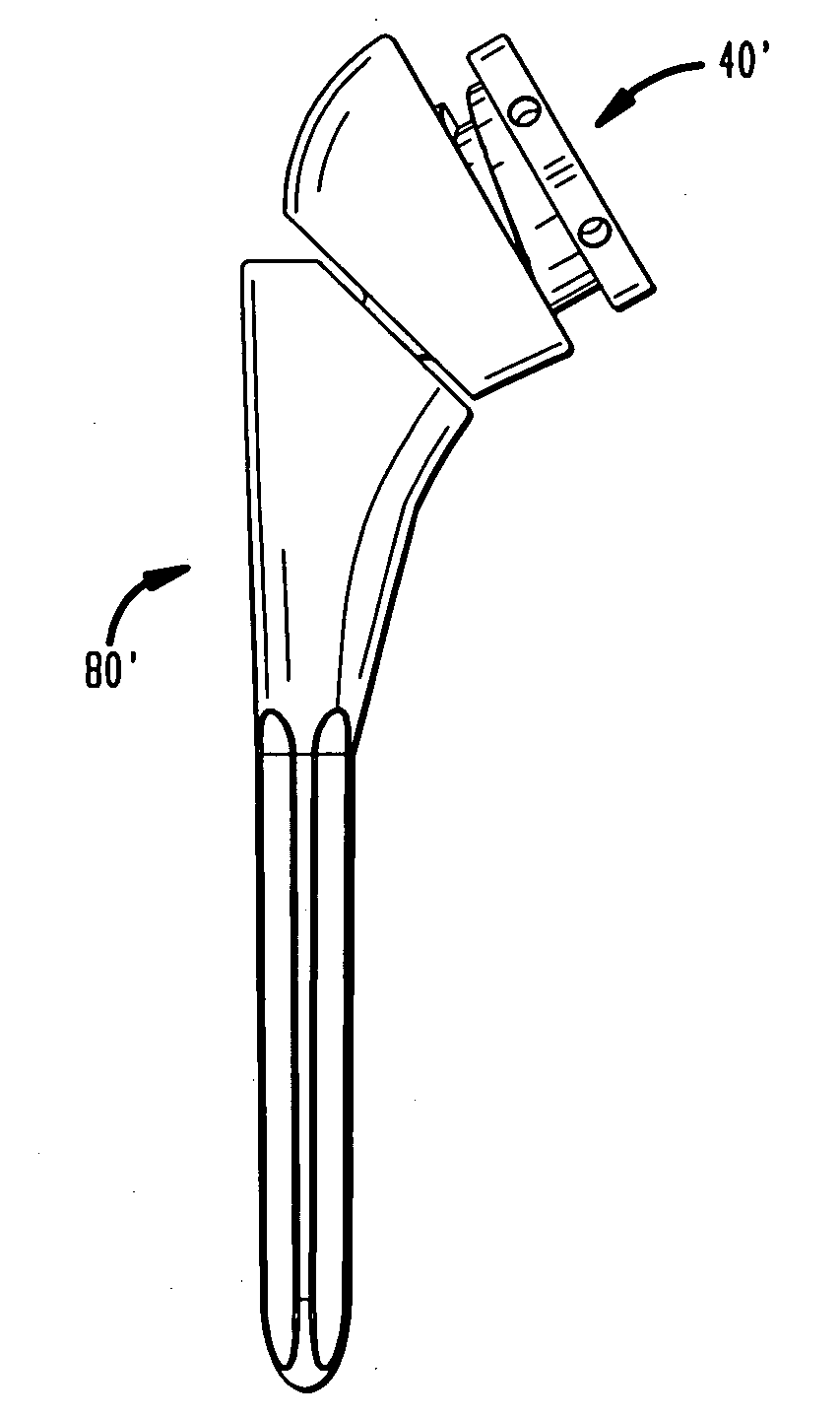
Figure 1 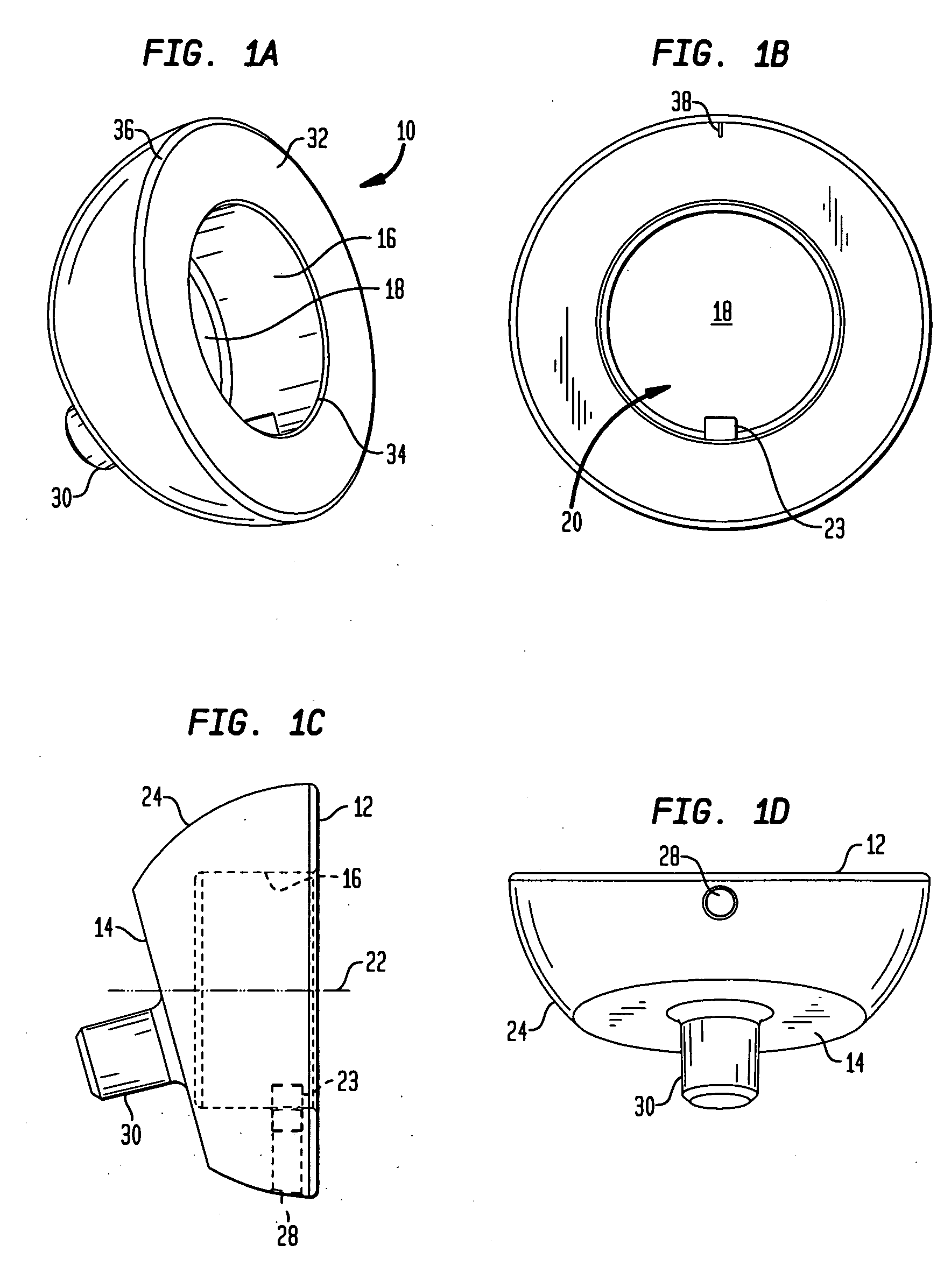
Figure 2 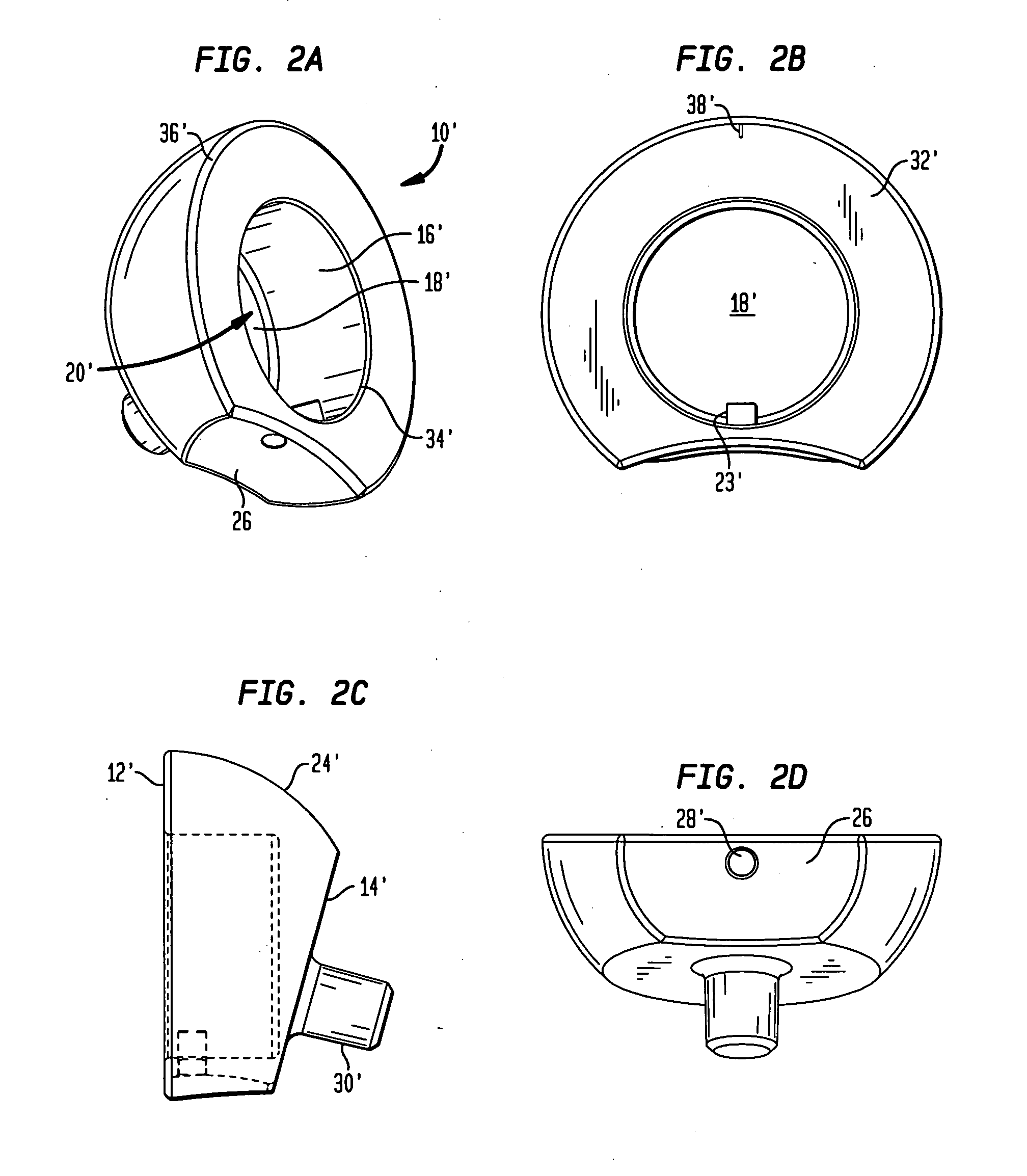
Figure 3
Abstract
Description
FIELD OF THE TECHNOLOGY
[0001] The present invention relates to an expandable reverse shoulder trial for reverse shoulder athroplasty (RSA), and in particular it relates to such a trial including an insert that rotatably engages a humeral cup.BACKGROUND OF THE INVENTION
[0002] The successful outcome of RSA depends greatly on proper soft tissue tension. Since the rotator cuff is either absent or severely compromised and irreparable, the stability of the shoulder joint comes from significant deltoid tension holding the ball and socket joint together.
[0003] Existing reverse shoulder systems require a surgeon to pick a trial liner and reduce the shoulder joint with that liner assembled into a humeral cup. If the correct liner is chosen, the soft tissue tension is significant, requiring the surgeon to apply extreme force to the humerus and surrounding soft tissues to reduce the joint. If no additional damage is done during this reduction process, the joint must then be dislocated to allow the...
Examples
Embodiment Construction
[0080]Referring to FIGS. 1A-1D, there is shown an embodiment of a humeral cup of the present invention designated generally by reference numeral 10. As shown in those figures, cup 10 includes a proximal end 12 and a distal end 14. Cup 10 preferably further includes a circular wall 16 and a base 18 defining a recess 20. Recess 20 defines a central axis 22 as shown in FIG. 1C. Preferably, a guide portion 23 protrudes from wall 16. Guide portion 23 is preferably configured as a pin.
[0081]In the preferred embodiment, proximal end 12 and distal end 14 of cup 10 are not coplanar. Between distal end surface 14 and proximal end surface 12 is a hemispherical outer surface 24. In an alternative embodiment, as shown in FIGS. 2A-2D, a cup 10′ further includes a concave surface 26 located between a proximal end surface 12′ and a distal end surface 14′. Surface 26 faces medially and is preferably configured to allow for greater articulation of cup 10′ with respect to a scapula bone after cup 10′ ...