

Quick change spindle
a spindle and spindle technology, applied in the direction of control mechanisms, turning machine accessories, program control, etc., can solve the problems of increasing the cost of manual actuation of the mechanism, reducing the efficiency of processes, so as to reduce the potential for human error, reduce the time of tool changeover, and improve the effect of assembly cycle times
Patent Information
- Authority / Receiving Office
- US · United States
- Patent Type
- Applications(United States)
- Current Assignee / Owner
- Publication Date
- 2009-06-04
- Estimated Expiration
- Not applicable · inactive patent
Smart Images
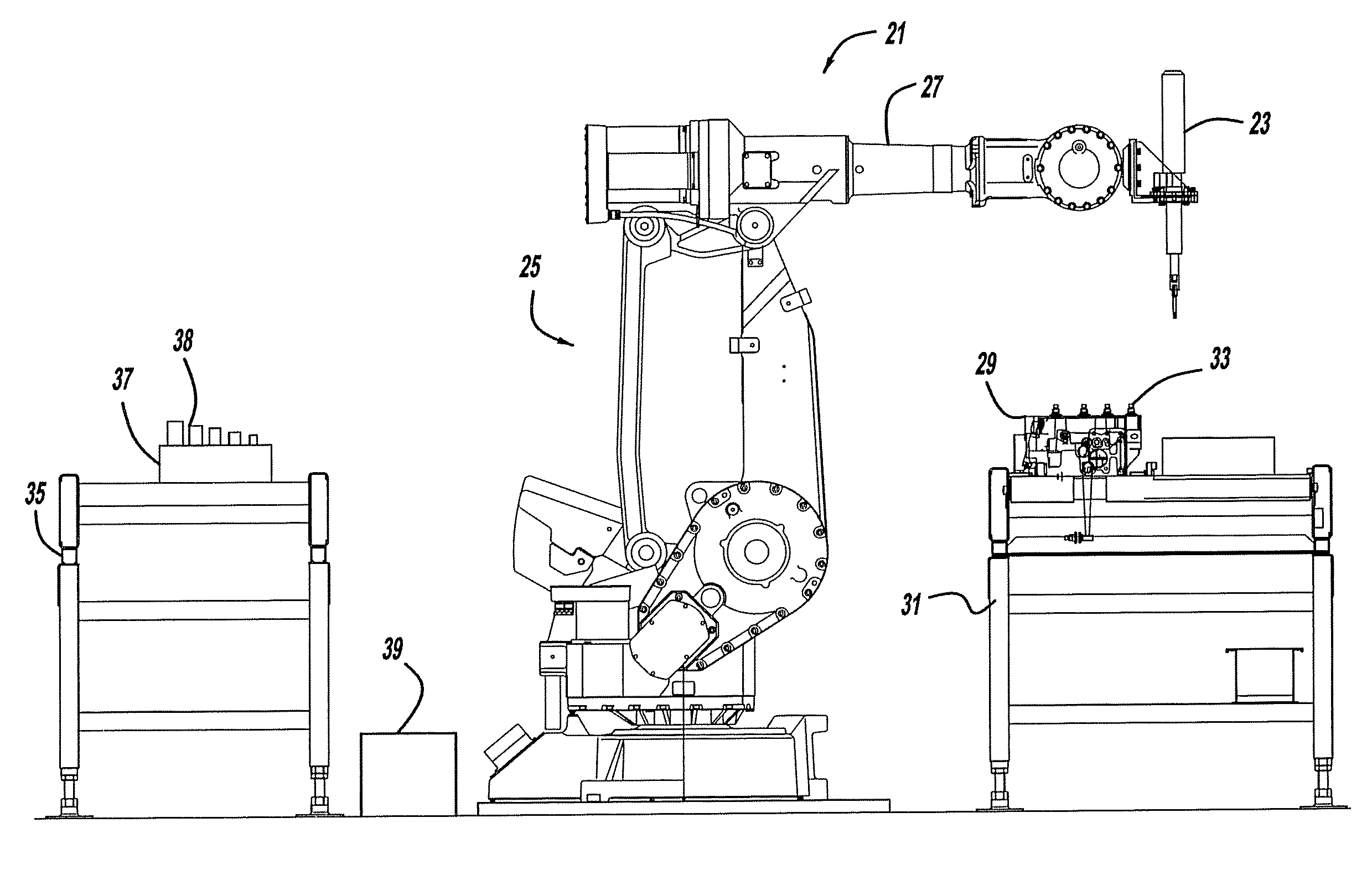
Figure 1 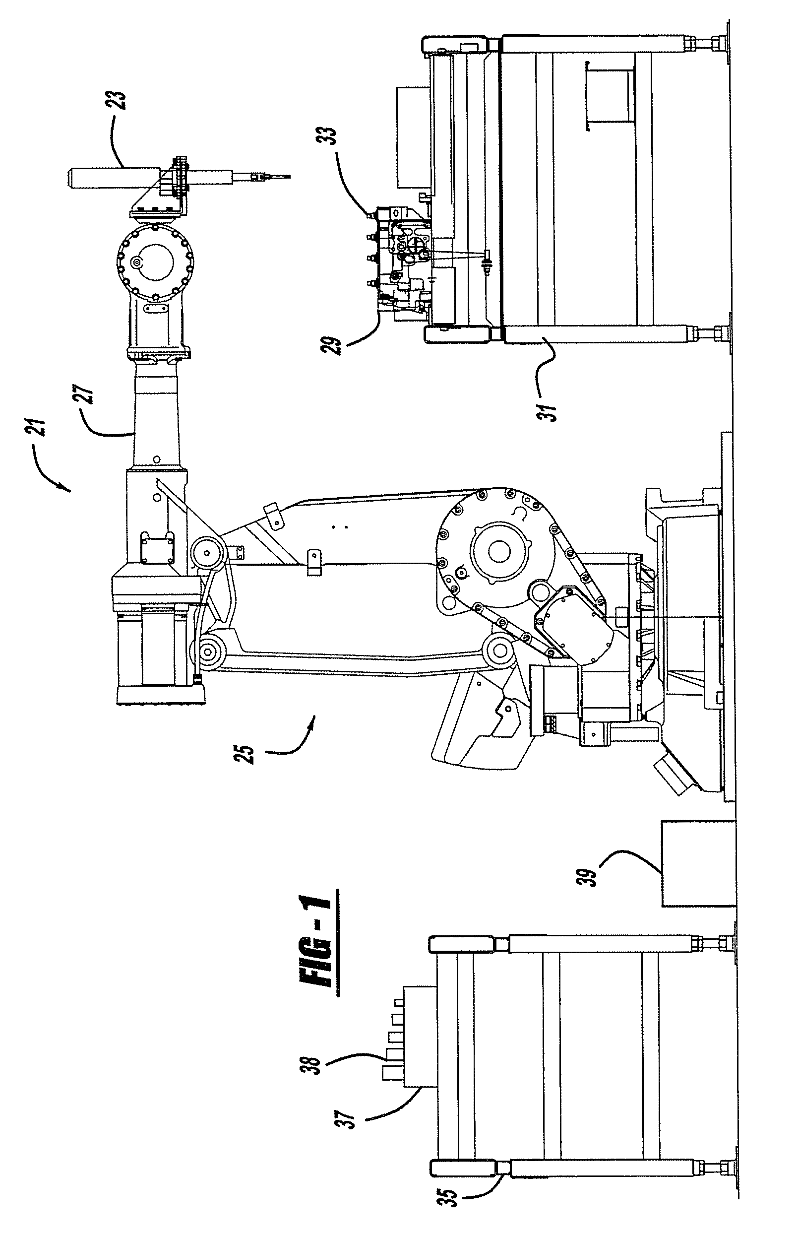
Figure 2 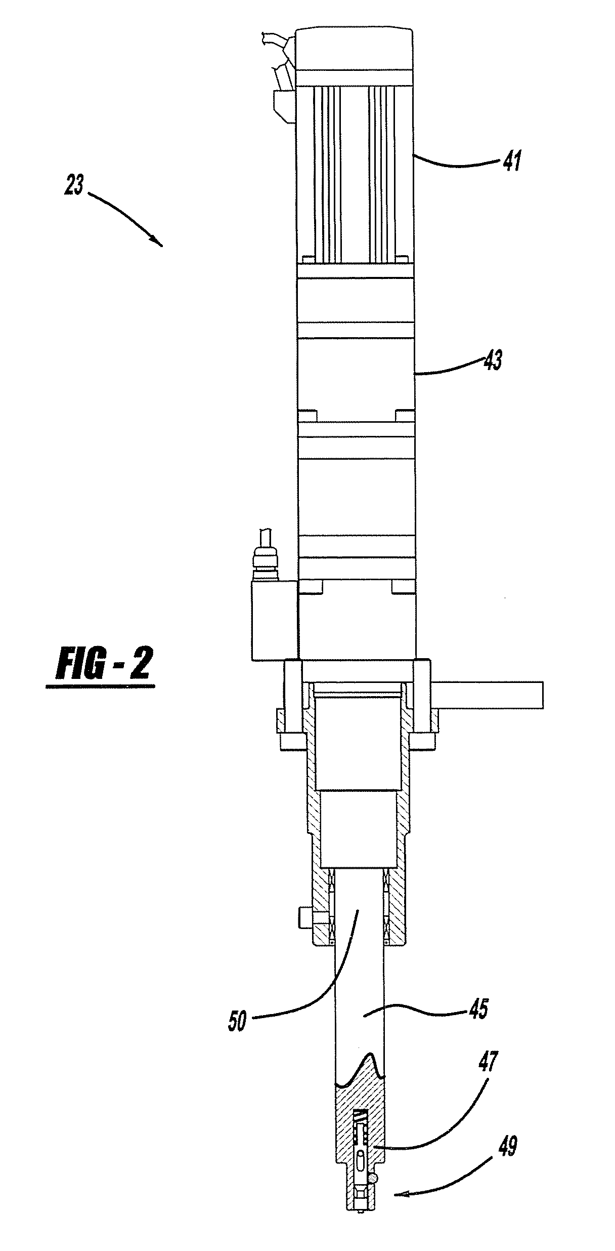
Figure 3
Abstract
Description
BACKGROUND AND SUMMARY OF THE INVENTION
[0001] The present invention relates to automated tool systems having interchangeable fastener drivers and more particularly to a device and method for automating the process of changing fastener drivers on an automated tool system.
[0002] In many assembly processes, a tool system may need to perform several different operations on fasteners of different geometries, each requiring a unique fastener driver. Past tool systems required manual intervention to change a fastener driver to perform a new operation or multiple separate drivers were employed. Manually changing fastener drivers, however, often decreases the efficiency of processes, and the sequence of tasks performed by a particular system may require multiple fastener drivers or multiple tool systems, thus further complicating and slowing the assembly cycle and / or increasing expense. As assembly cycle times continue to improve, an automated tool system is needed to decrease the time to chan...
Examples
Embodiment Construction
[0020]FIG. 1 shows a work station 21 in an assembly plant that employs the preferred embodiments of a quick change spindle assembly 23. An articulated or gantry robot 25 has an arm 27 that holds spindle assembly 23. Robot arm 27 moves spindle assembly 23 into various positions to perform operations on a work piece 29 located on a conveyor 31. An exemplary conveyor is disclosed in U.S. Pat. No. 6,705,454, entitled “Accumulating Power Roll Conveyor System” which issued to Fishaw et al. on Mar. 16, 2004, which is incorporated by reference herein. The work piece 29 is preferably a powertrain component such as an automotive vehicle engine block but may alternately be another component having fasteners 33. Robot arm 27 also moves spindle assembly 23 to a stand 35 where a holder assembly 37 accommodates multiple fastener drivers 38. A computer microprocessor 39 or other programmable controller includes software instructions which control robot 25, spindle assembly 23, and holder assembly 3...