
Flow straightening apparatus
a flow straightening and apparatus technology, applied in the field of fluid flow mechanics, can solve problems such as unstable flow and irregular flow, and achieve the effects of convenient, economical and universally adapted to resolution, and more economical construction
Patent Information
- Authority / Receiving Office
- US · United States
- Patent Type
- Applications(United States)
- Current Assignee / Owner
- Publication Date
- 2010-09-09
Smart Images
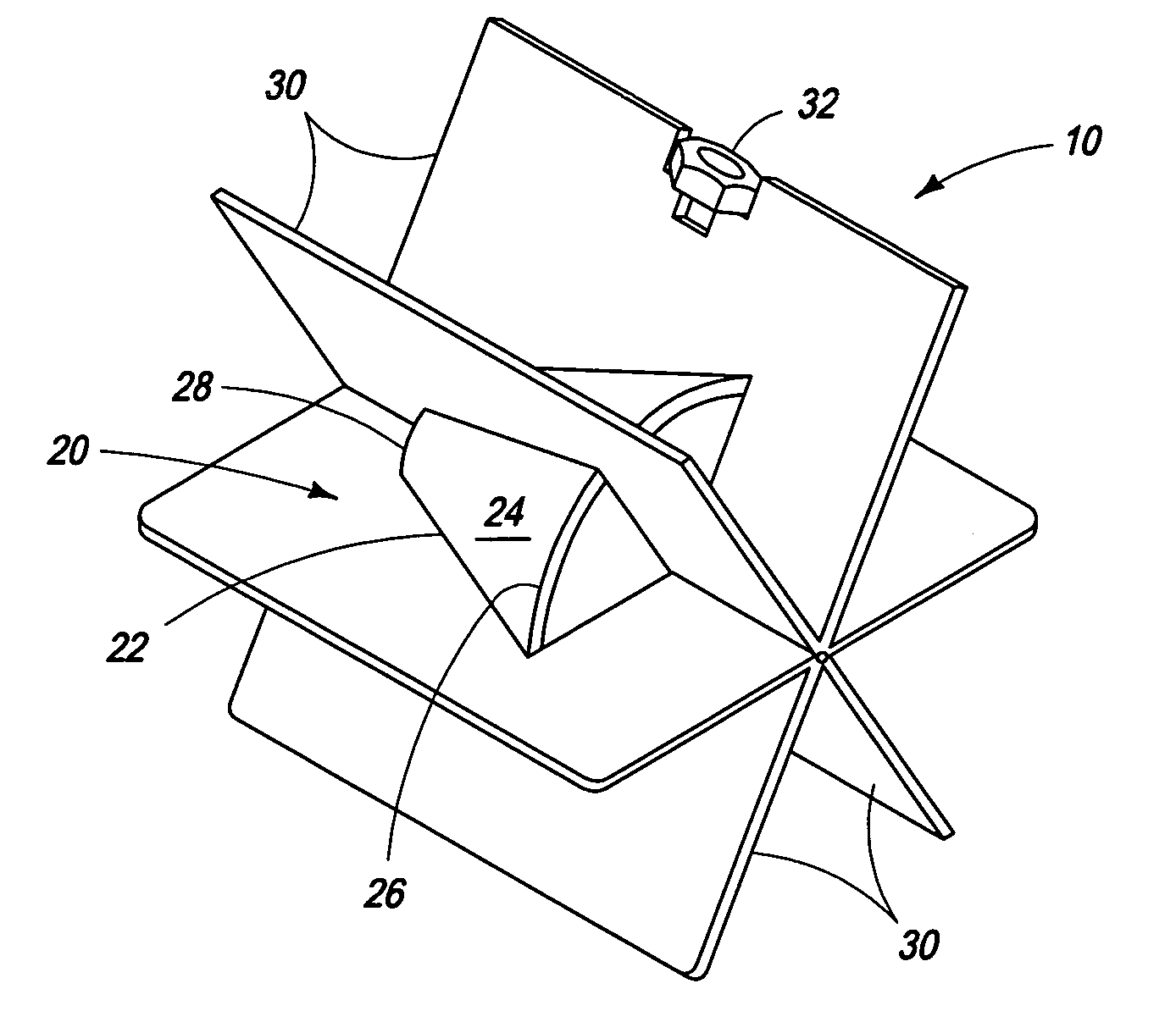
Figure 1 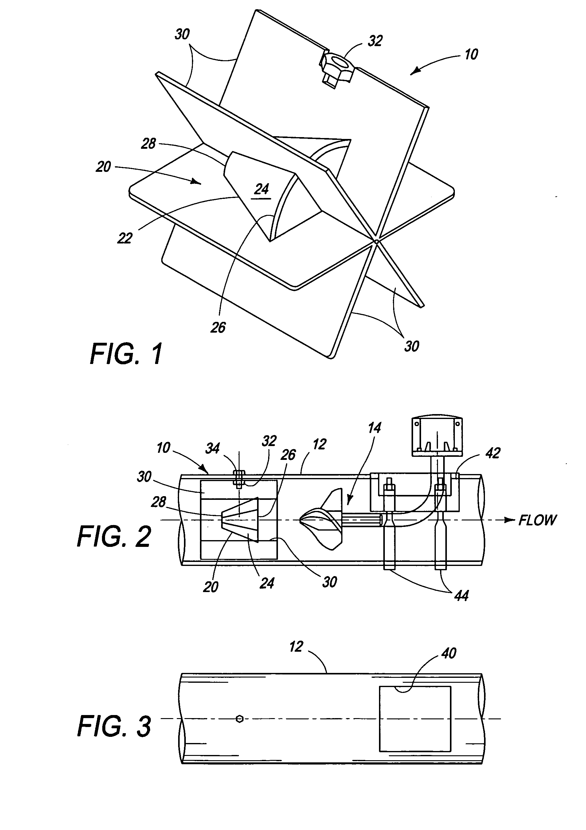
Figure 2 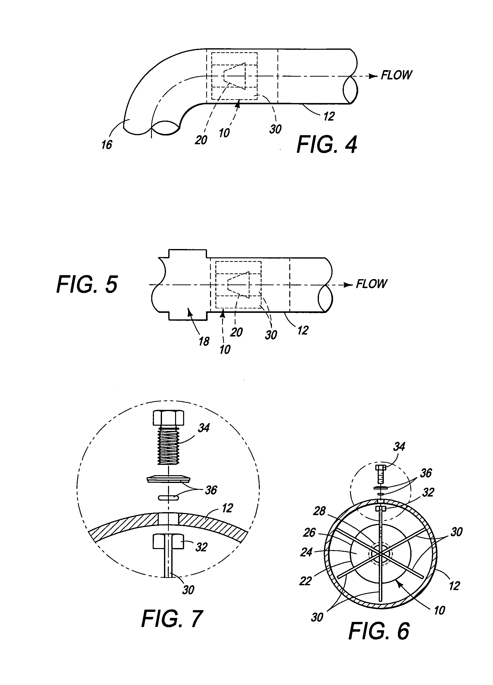
Figure 3
Abstract
Description
PRIORITY CLAIM
[0001] The present application claims priority to and the benefit of U.S. Provisional Application No. 60 / 930,802 filed on May 18, 2007.FIELD OF THE INVENTION
[0002] The present invention relates to fluid flow mechanics, and more particularly, to apparatus, commonly known as flow straighteners, for converting fluid flow in a conduit from unstable and / or distorted conditions to uniform, stable and consistent flow conditions.BACKGROUND OF THE INVENTION
[0003] For a variety of reasons, for example, accurate measurement of fluid flow through a conduit or pipeline, such as an irrigation water pipeline, it is desirable that the fluid flowing through the conduit have a substantially flat face velocity profile of maximum mean flow diameter, i.e., a diameter approaching or approximating the inner diameter of the conduit.
[0004] Frequently, departures from the optimum occur. The velocity profile maybe become convex or concave, or asymmetrical, or symmetrical but non-uniform, or the flow...
Examples
Embodiment Construction
[0028]The following is a description of an embodiment of the invention presently contemplated by the inventor to be the best mode of carrying out his invention.
[0029]As shown in FIGS. 2, 4 and 5, the flow straightener of the invention, indicated generally at 10, is adapted to be installed in a pipe or conduit 12, notably an irrigation pipeline 12. The flow straightener 10 is especially adapted for installation upstream from a fluid flow meter 14 as shown in FIG. 2, or downstream from a curve, bend or elbow 16 in the pipeline 12, as shown in FIG. 4, or downstream from a flow disturbing pipe component such as valve 18, as shown in FIG. 5. The valve 18 may for example comprise an irrigation system check valve installed in and comprising part of an irrigation water distribution system pipeline 12.
[0030]In summary, the straightener 10 is adapted to be installed in any new or existing pipeline downstream from any disturbance causing device or upstream from any locale in which it is desire...