
Weight measurement device
a weight measurement and weight technology, applied in the direction of measurement devices, weighing apparatus details, instruments, etc., can solve the problem of enlargement of the entire thickness of the weight measurement devi
Patent Information
- Authority / Receiving Office
- US · United States
- Patent Type
- Applications(United States)
- Current Assignee / Owner
- Publication Date
- 2011-09-01
Smart Images
Figure 1 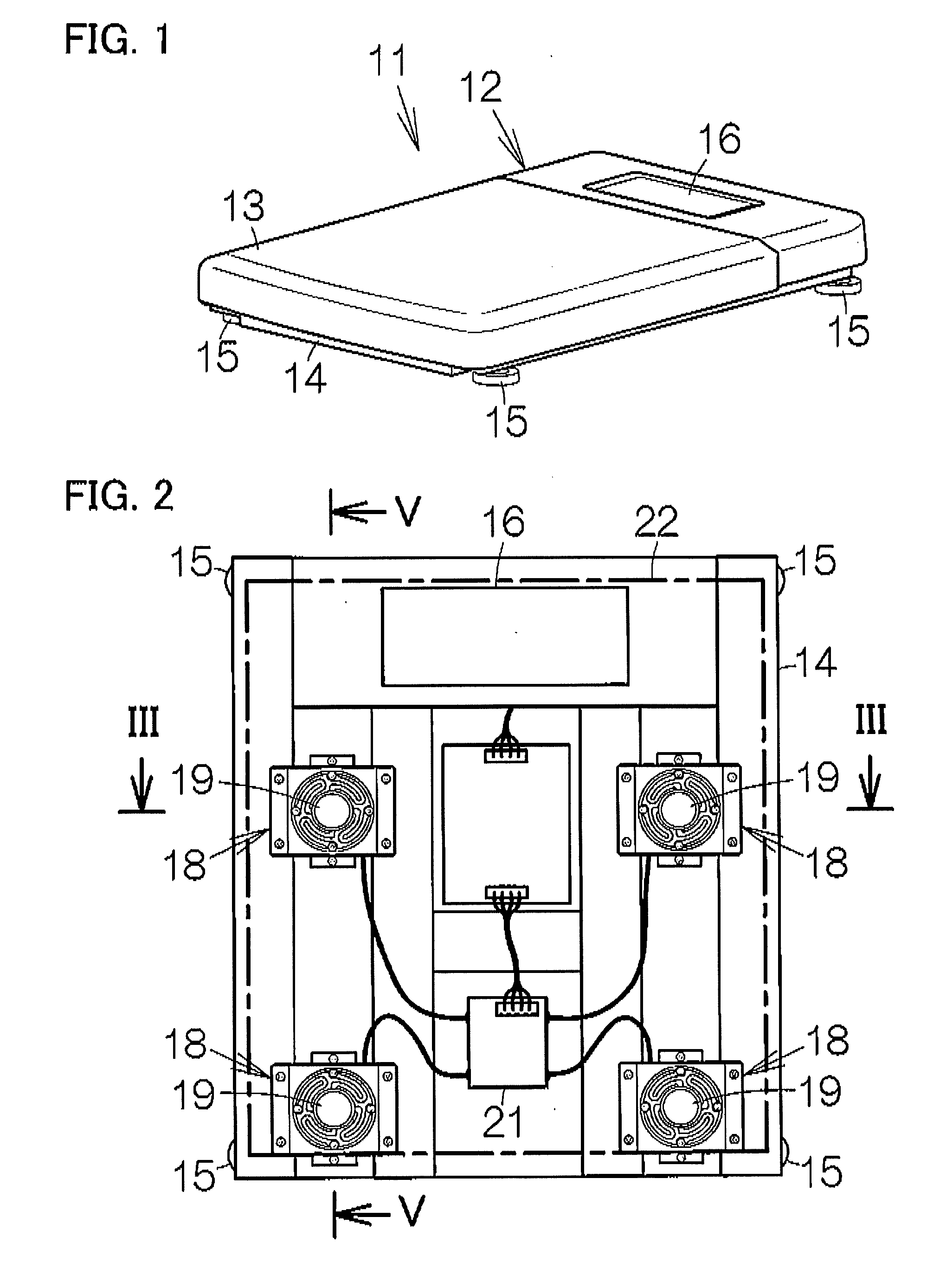
Figure 2 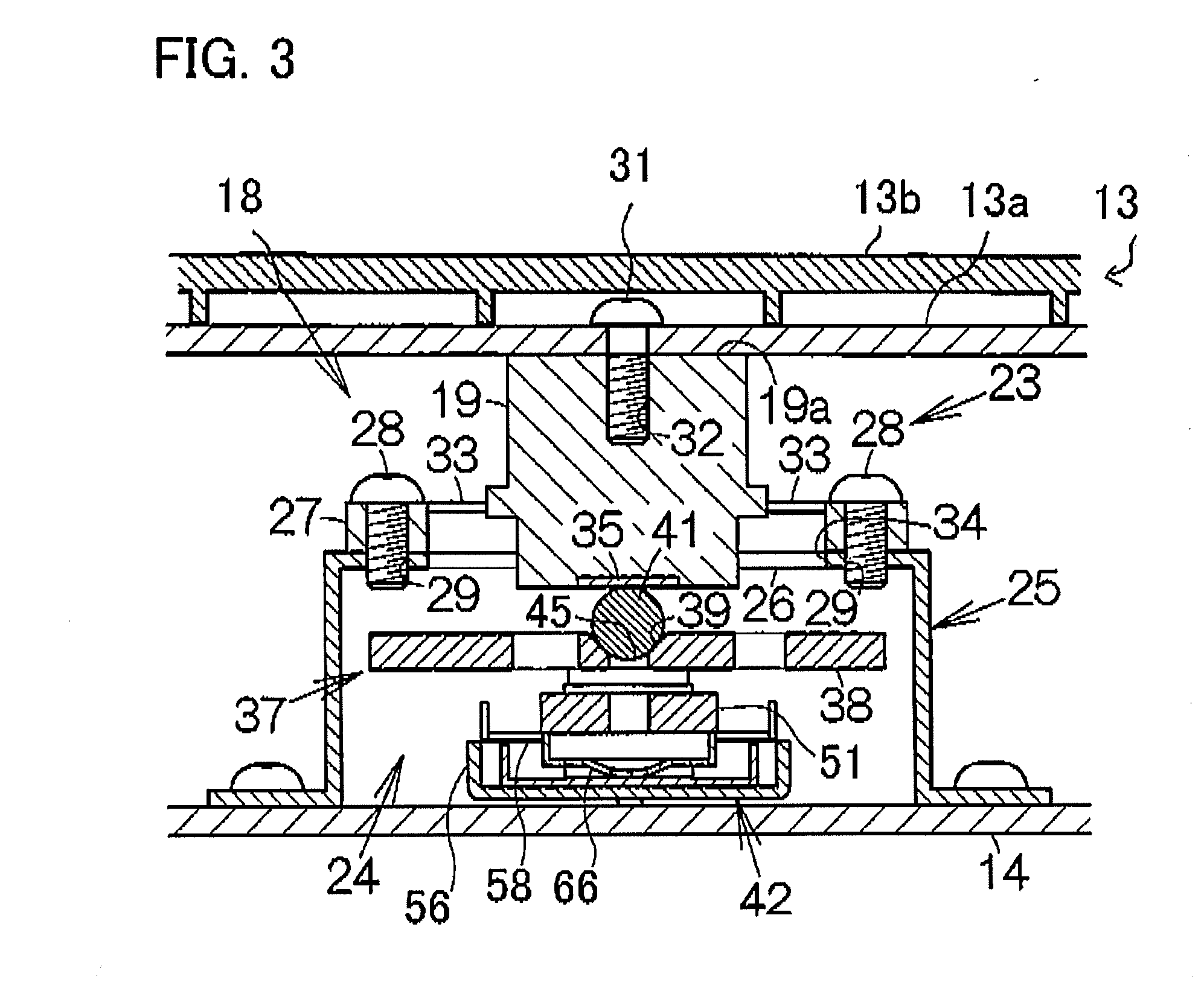
Figure 3
Abstract
Description
BACKGROUND OF THE INVENTION
[0001] 1. Field of the Invention
[0002] The present invention relates to weight measurement devices, for example, weighing scales.
[0003] 2. Related Art
[0004] In a conventional weighing scale, there may be a chamber defined by a base and a platform on which a subject stands, and one or more load cells are contained in the chamber as disclosed in JP 2003-307454-A and JP 2004-156937-A. The load cell generates an electric signal due to the weight exerted on the platform. On the basis of the electric signal, the amount of weight on the platform is calculated.
[0005] The load cell incorporates a flexure element having a fulcrum point supported with respect to the base and a force point (application point of the force) coupled to the platform. When a load is applied to the force point from the platform, the part of the flexure element between the force point and the fulcrum point deforms, and the degree of deformation is measured with a suitable element, for example, a ...
Examples
Embodiment Construction
[0021]FIG. 1 shows a weight measurement device, i.e., a weighing scale 11 according to an embodiment of the present invention. The weighing scale 11 includes a housing 12 including a platform 13 that includes an upper surface that may be planer and horizontal. A user of the weighing scale 11 stands on the platform 13.
[0022]The housing 12 includes a base 14. The base 14 is made of a rigid material, for example, stainless steel. The base 14 is formed into a substantially rectangular shape in plane view as shown in FIG. 2. At the four corners of the rectangular shape, legs 15 are fixed. The length of each leg 15 with respect to the base 14 may be adjustable, so that the orientation of the platform 13 can be adjusted with respect to the horizontal and the upper planar surface of the platform 13 can be deployed horizontally. Such adjustment of the length of each leg 15 is achieved by, for example, providing each leg with a screw having a vertically oriented axis.
[0023]The platform 13 cov...