
Drive device, print head and image forming apparatus
a technology of drive circuit and print head, which is applied in the direction of recording apparatus, instruments, electrographic processes, etc., can solve the problems of negative resistance region oscillation of drive current and change of exposure energy, so as to prevent variations of exposure energy, and prevent oscillation of drive circuit
Patent Information
- Authority / Receiving Office
- US · United States
- Patent Type
- Applications(United States)
- Current Assignee / Owner
- Publication Date
- 2011-09-29
Smart Images
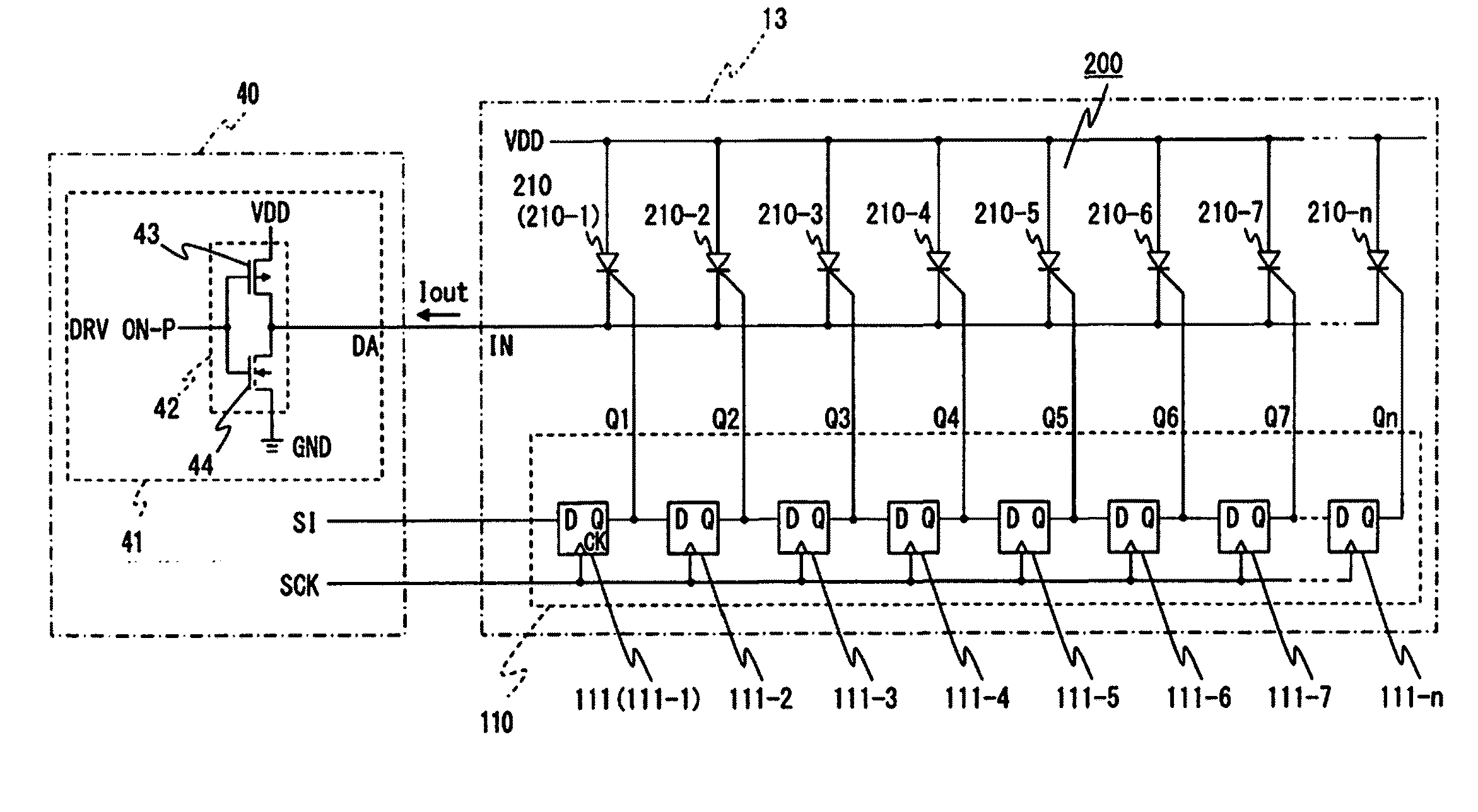
Figure 1 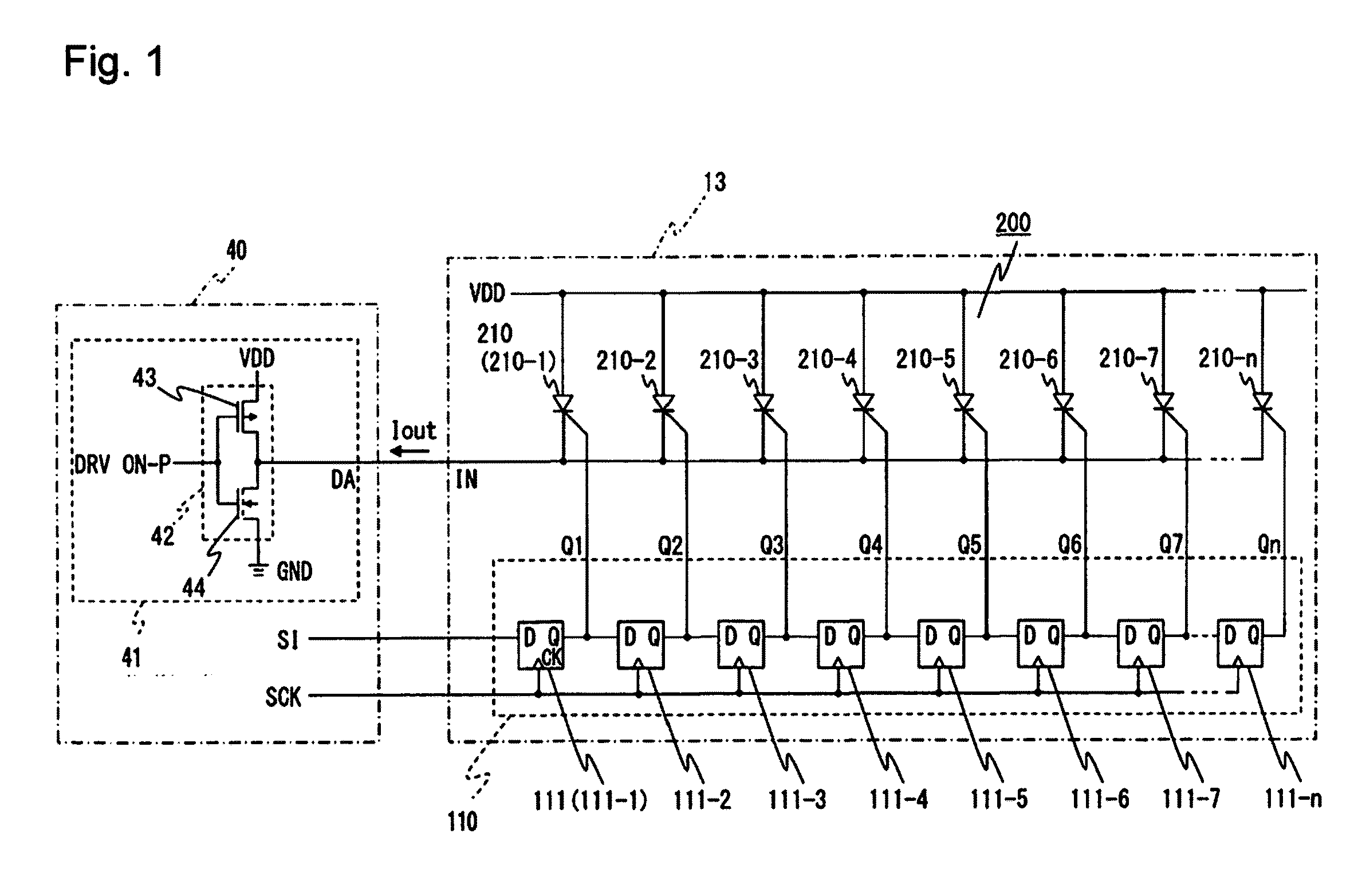
Figure 2 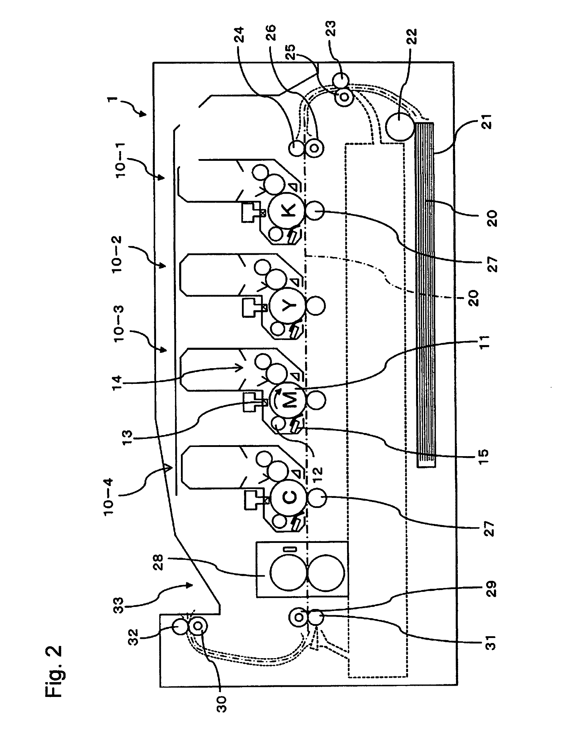
Figure 3
Abstract
Description
CROSS REFERENCE TO RELATED APPLICATIONS
[0001] This application claims priority based on 35 USC 119 from prior Japanese Patent Application No. 2010-067335 filed on Mar. 24, 2010, entitled “DRIVE DEVICE, PRINT HEAD AND IMAGE FORMING APPARATUS”, the entire contents of which are incorporated herein by reference.BACKGROUND OF THE INVENTION
[0002] 1. Field of the Invention
[0003] The invention relates to a drive device which selectively and cyclically drives a group of three-terminal light emitting elements such as light emitting thyristors, a print head including the drive device, and an image forming apparatus such as an electrophotographic printer including the print head.
[0004] 2. Description of Related Art
[0005] Conventionally, as a drive device provided in an image forming apparatus such as an electrophotographic printer, the following configuration has been known for driving a light emitting thyristor array in which a large number of light emitting thyristors are arranged. The configurati...
Examples
embodiment 1
[0027](Image Forming Apparatus According to Embodiment 1)
[0028]FIG. 2 is a schematic configuration diagram of an image forming apparatus according to Embodiment 1 of the invention.
[0029]Image forming apparatus 1 is a tandem type electrophotographic color printer provided with an exposure device (for example, a print head) including a light emitting element array as a three-terminal switch element array using driven elements (for example, light emitting thyristors each of which is a three-terminal switch element as a light emitting element). Image forming apparatus 1 includes four process units 10-1 to 10-4, which are disposed in that order from upstream of the transport path of recording medium 20 (for example, paper) so as to respectively form black (K), yellow (Y), magenta (M) and cyan (c) images. The common internal configuration of process units 10-1 to 10-4 is described by citing process unit 10-3 for magenta as an example.
[0030]Process unit 10-3 includes photosensitive body 11...
embodiment 2
[0153](Printing Controller and Print Head According to Embodiment 2)
[0154]FIG. 11 is a block diagram illustrating a schematic circuit configuration of a printing controller and a print head according to Embodiment 2 of the invention, in which common signs are assigned to elements common to those of Embodiment 1 shown in FIG. 1.
[0155]In image forming apparatus 1 according to Embodiment 2, the circuit configuration of printing controller 40A and print head 13A are different from that of printing controller 40 and print head 13 according to Embodiment 1.
[0156]Print head 13A according to Embodiment 2 includes shift register 110A of the self scanning type whose configuration is different from shift register 110 of Embodiment 1 and light emitting element array 200 and the like which are the same as those of Embodiment 1.
[0157]Self scanning type shift register 110A is a circuit to supply trigger current to light-emitting element array 200 to turn light-emitting element array 200 on and off...
embodiment 3
[0201](Printing Controller and Print Head According to Embodiment 3)
[0202]FIG. 13 is a block diagram illustrating a schematic circuit configuration of a printing controller and a print head in Embodiment 3 of the invention, in which common signs are assigned to elements common to those in FIG. 1 showing Embodiment 1.
[0203]In image forming apparatus 1 according to Embodiment 3, a circuit configuration of print head 13B and printing controller 40B is different from print head 13 and printing controller 40 according to Embodiment 1.
[0204]Print head 13B according to Embodiment 3 includes shift register 110 similar with Embodiment 1 and light emitting element array 200B of a configuration different from light emitting element array 200 according to Embodiment 1.
[0205]Light emitting element array 200B includes three-terminal light emitting elements which are, for example, a plurality of N-gate type light emitting thyristors 210B (210B-1 to 210B-n, . . . ). A first terminal (for example, c...