
Image acquisition system and method for the manufacture thereof
a technology of image acquisition and acquisition system, applied in the field of image acquisition system, can solve the problems of laborious assembly and adjustment, relatively complex construction,
Patent Information
- Authority / Receiving Office
- US · United States
- Current Assignee / Owner
- Publication Date
- 2011-10-27
- Estimated Expiration
- Not applicable · inactive patent
Smart Images
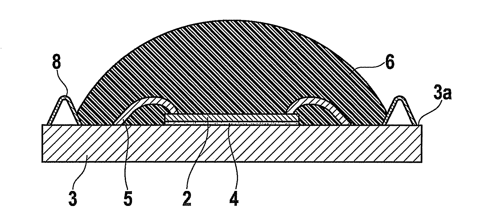
Figure 1 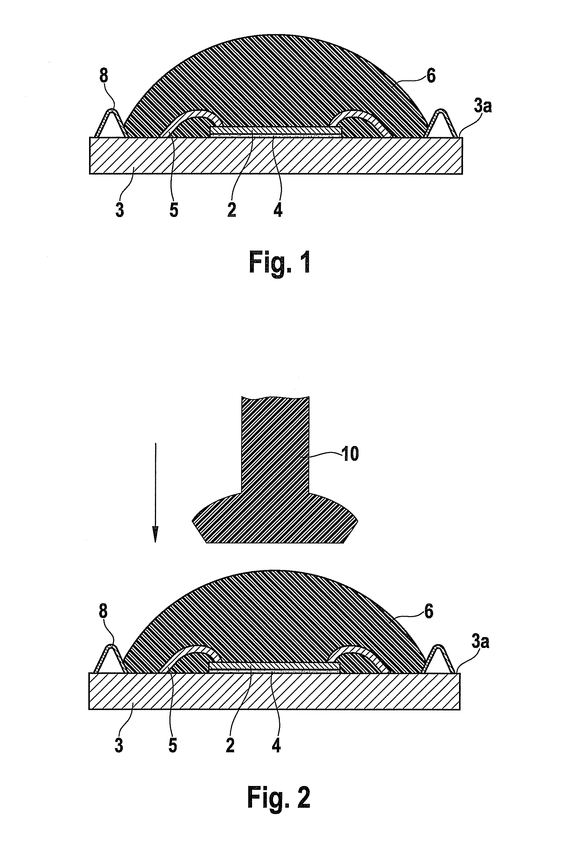
Figure 2 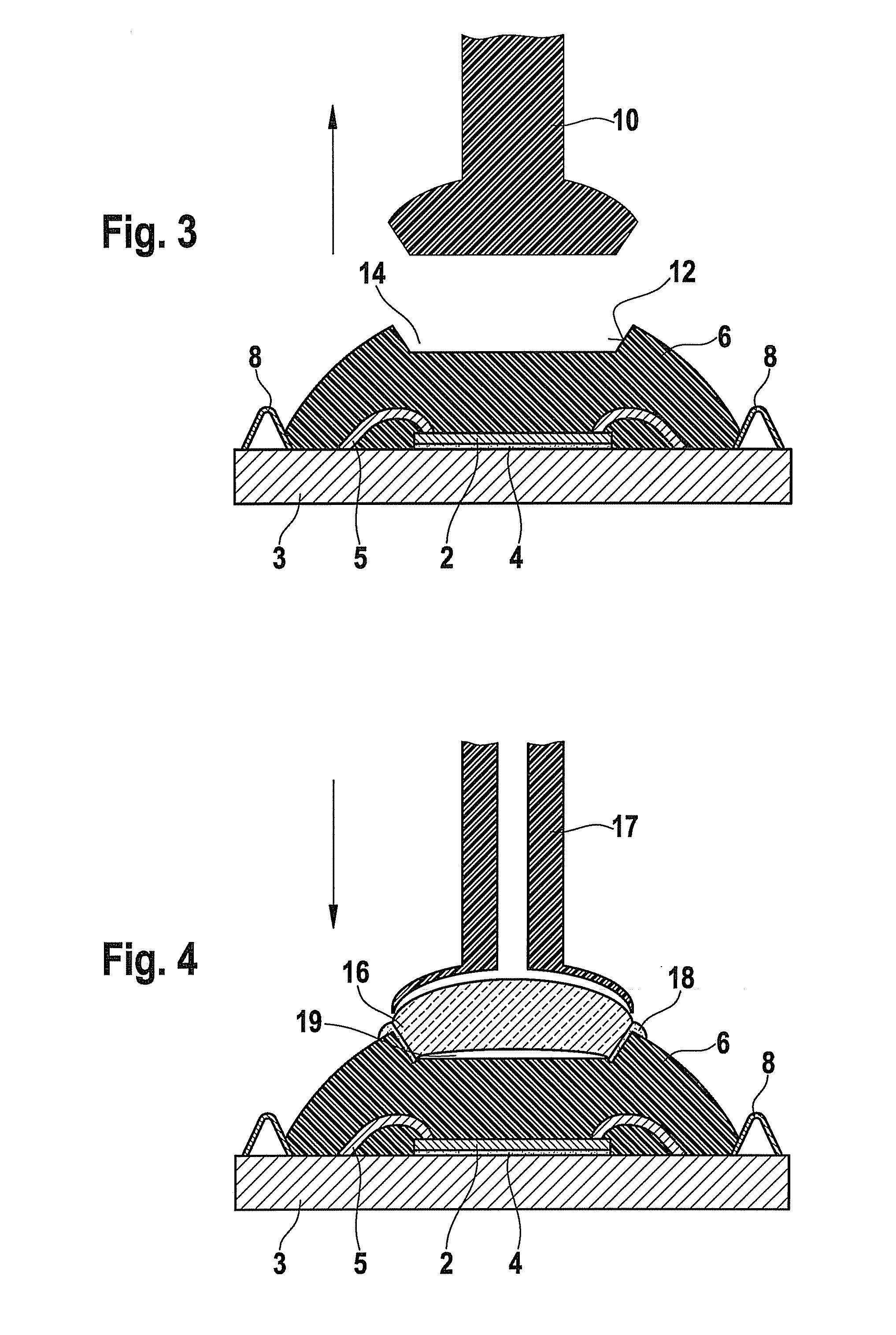
Figure 3
Abstract
Description
FIELD OF THE INVENTION
[0001] The present invention relates to an image acquisition system and to a method for the manufacture thereof.BACKGROUND INFORMATION
[0002] WO 2005 / 015897 discloses an image acquisition system that has an image sensor, an optical unit, a housing, and securing means for immobilizing the image sensor relative to the housing. Provided in the interior of the housing are alignment means that enable unsecured axial alignment of the main axes of the image sensor and optical unit with respect to one another. A threaded receptacle is advantageously provided as a means for receiving the optical unit of the housing.
[0003] An image acquisition system of this kind enables excellent optical accuracy. The construction is relatively complex, however, and generally requires laborious assembly and adjustment.SUMMARY
[0004] Example embodiments of the present invention provide that a sealing compound is applied on the image sensor and its contact points on the substrate, which compoun...
Examples
Embodiment Construction
[0020]In order to manufacture an image acquisition system 1 shown in FIG. 5, according to FIG. 1 firstly an imager chip 2 constituting an image sensor is secured on upper substrate side 3a of a substrate 3, e.g. a circuit board 3, by way of, for example, an adhesive layer 4, and is contacted via bonding wires 5. A sealing compound (glob top) is then applied onto upper substrate side 3a such that it completely covers imager chip 2 and its wire bonds 5. A delimiter 8 for delimiting the applied sealing compound 6 is advantageously provided on upper substrate side 3a. Delimiter 8 can be embodied, as shown in FIG. 1, in particular by a rim 8 configured peripherally, i.e. in particular annularly, on substrate 3. Also possible, however, are stop edges at which excess material is discharged to the side in the event of an overflow.
[0021]As shown in FIG. 1, sealing compound 6 is advantageously applied in liquid or viscous or pasty fashion in a convex shape, e.g. droplet shape, which is promot...