
Speed or torque probe for gas turbine engines
a technology of speed or torque and gas turbine engine, which is applied in the direction of work measurement, measurement devices, instruments, etc., can solve the problems of additional modulations or microphonies, the output of variable reluctance sensors is not working properly, and the pole piece is significantly damaged by external vibration, so as to minimise the transfer of strain and reduce the effect of strain transfer
Patent Information
- Authority / Receiving Office
- US · United States
- Current Assignee / Owner
- Publication Date
- 2011-12-22
Smart Images
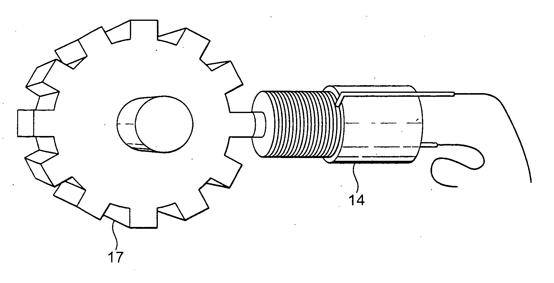
Figure 1 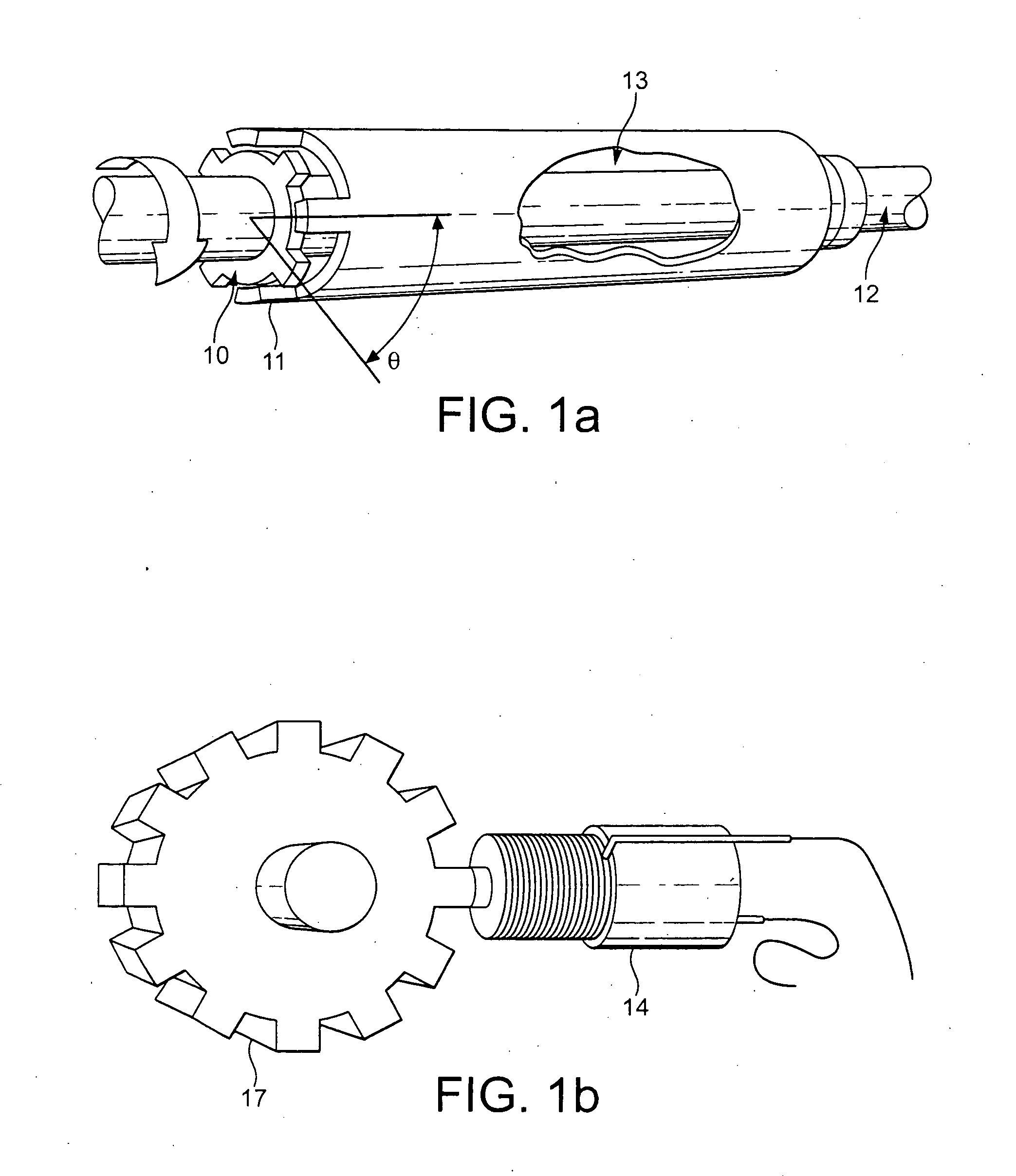
Figure 2 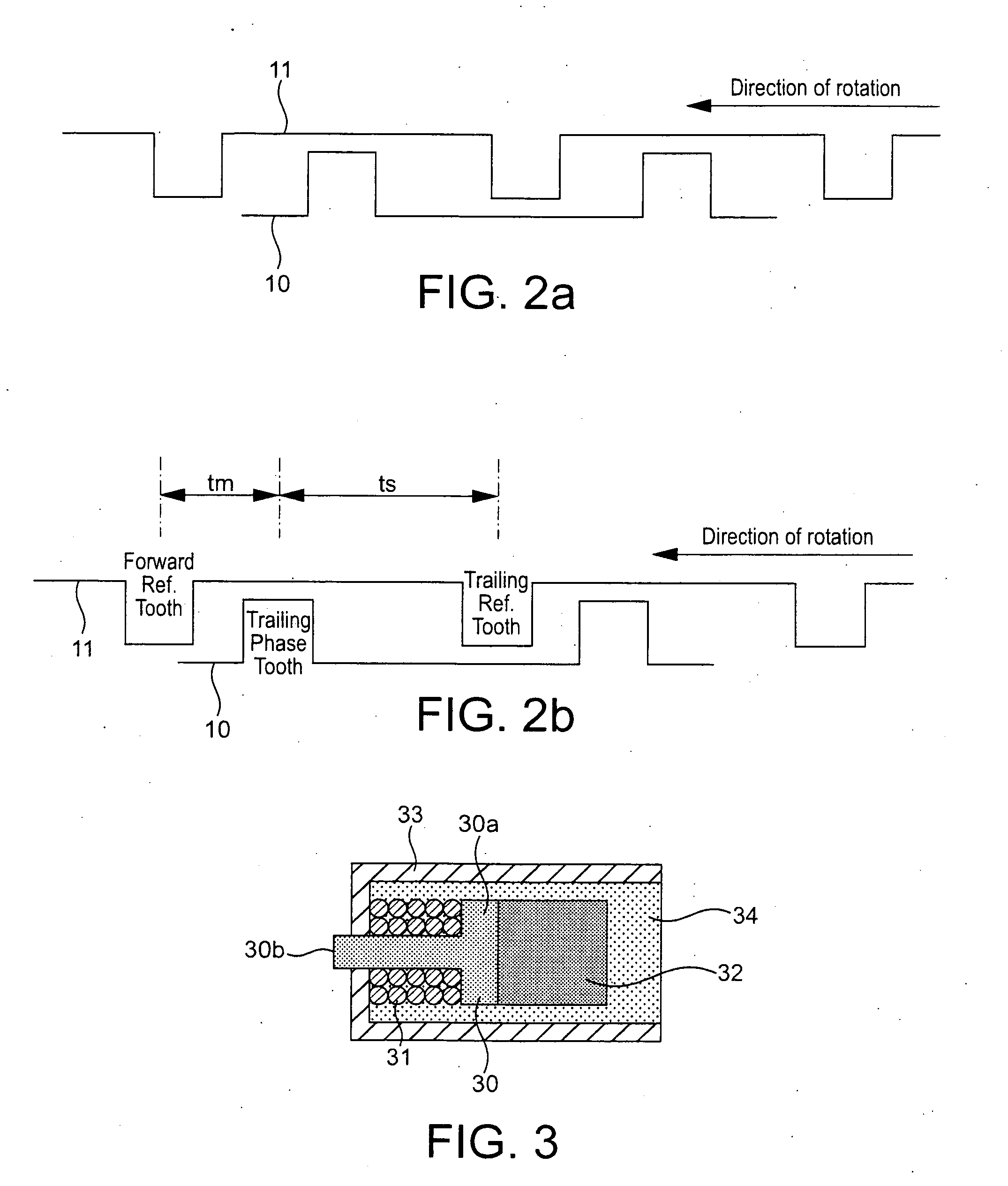
Figure 3
Abstract
Description
FIELD OF THE INVENTION
[0001] The present invention relates to variable reluctance probes used for measuring the speed and torque applied to rotating shafts. Probes of this type are typically found in gas turbine engines or in gear boxes used in aircraft.BACKGROUND TO THE INVENTION
[0002] Variable reluctance sensors are used to monitor both the speed of rotating shafts and the torque loading on shafts in gas turbine engines and gear boxes connected to gas turbine engines. For example, FIG. 1 illustrates an assembly for monitoring the torque loading on a power transmission shaft between a gas turbine and the power gearbox that drives the propeller.
[0003] When a load is applied to a power transmission shaft it will twist. For a known modulus of elasticity and at a constant temperature, the amount of twist (A) is proportional to the torque transmitted. This basic principle is used to measure torque.
[0004] The assembly shown in FIG. 1a comprises two intermeshed phonic wheels 10, 11, attached ...
Examples
Embodiment Construction
[0053]The basic arrangement for a variable reluctance sensor for detecting speed or torque in a gas turbine engine or gear box connected to a gas turbine engine has been described previously with reference to FIGS. 1 to 3. The problem of unwanted microphony in the output signal from such variable reluctance sensors, resulting from strain in the magnetic pole piece 30, has also been described.
[0054]FIG. 6 illustrates a variable reluctance sensor as shown in FIG. 3, but illustrating the direction of the strain in the pole piece 30, which affects the nature of the output signal from conductive wire 31. The pole piece is formed from a soft magnetic material, is roughly T-shaped in cross-section and has a longitudinally extending shaft around which the conductive wire is wound and a rear head, against which the permanent magnet 32 is positioned. Current induced in the wire 31 as result of changes in the reluctance of the circuit formed by the magnetic pole piece, the phonic wheel, and ai...