
Axial gap rotating electrical machine
a technology of axial gap and electrical machine, which is applied in the direction of dynamo-electric machines, electrical apparatus, magnetic circuit shapes/forms/construction, etc., can solve the problems of increasing vibration and noise, increasing the mechanical strength of the joints, and increasing the number of assembly parts, so as to reduce the number of man-hours in assembling a motor, the effect of simplifying the manufacturing process of the motor
Patent Information
- Authority / Receiving Office
- US · United States
- Patent Type
- Applications(United States)
- Current Assignee / Owner
- Publication Date
- 2012-03-01
Smart Images
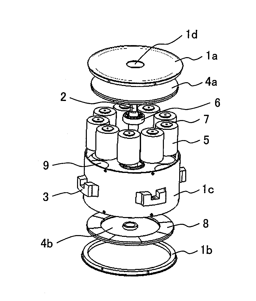
Figure 1 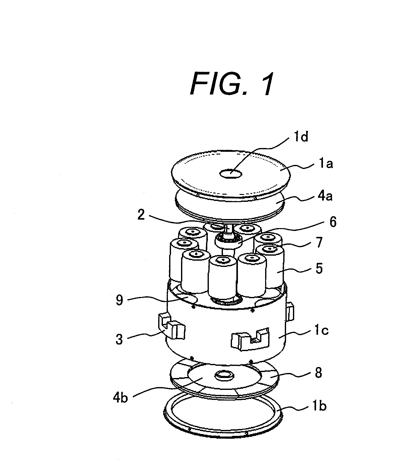
Figure 2 
Figure 3
Abstract
Description
CLAIM OF PRIORITY
[0001] The present application claims priority from Japanese Patent application serial no. 2010-190343, filed on Aug. 27, 2010, the content of which is hereby incorporatedby reference into this application.FIELD OF THE INVENTION
[0002] The present invention relates to an axial gap rotating electrical machine.BACKGROUND OF THE INVENTION
[0003] In general, axial gap rotating electrical machines are comprised of : a pair of rotor having two circular disks provided on the respective opposite surfaces thereof with permanent magnets and a shaft coupling the circular disks together, located in the centers thereof; a stator made up of multiple cores and coils to which the permanent magnets are opposed with a gap in between; and a pair of bearings rotatably supporting both ends of the shaft and bearing holders holding them.
[0004] As an example of axial gap rotating electrical machines in which a rotor and a stator are arranged opposite to each other in the direction of the central...
Examples
embodiments
[0046]FIG. 2 illustrates the appearance and shape of an ordinary axial gap rotating electrical machine, which includes a shaft 2 extended upward in the center of a substantially cylindrical rotating electrical machine case 1 formed of nonmagnetic material . The shaft 2 maybe taken out of the rotating electrical machine case 1 on both sides; however, it is taken out only on one side in this example.
[0047]The rotating electrical machine case 1 is provided with attaching portions 3 for installing the rotating electrical machine. When the invention is applied to a motor, it is desirable that a nonmagnetic and nonconductive material, such as resin and ceramic, should be used for the case 1 for the prevention of production of eddy current loss. There is no limitation on the material of the attaching portions.
[0048]FIG. 1 is a development illustrating the arrangement of devices housed in the rotating electrical machine case 1. The rotating electrical machine case 1 is comprised of an upper...