
Light guide plate and backlight module
a technology of light guide plate and backlight module, which is applied in the direction of lighting and heating apparatus, instruments, mechanical equipment, etc., can solve the problems of loss of light energy and guide plate microstructure, and achieve the effects of low luminous efficiency, higher brightness and low cos
Patent Information
- Authority / Receiving Office
- US · United States
- Patent Type
- Applications(United States)
- Current Assignee / Owner
- Publication Date
- 2013-01-24
Smart Images
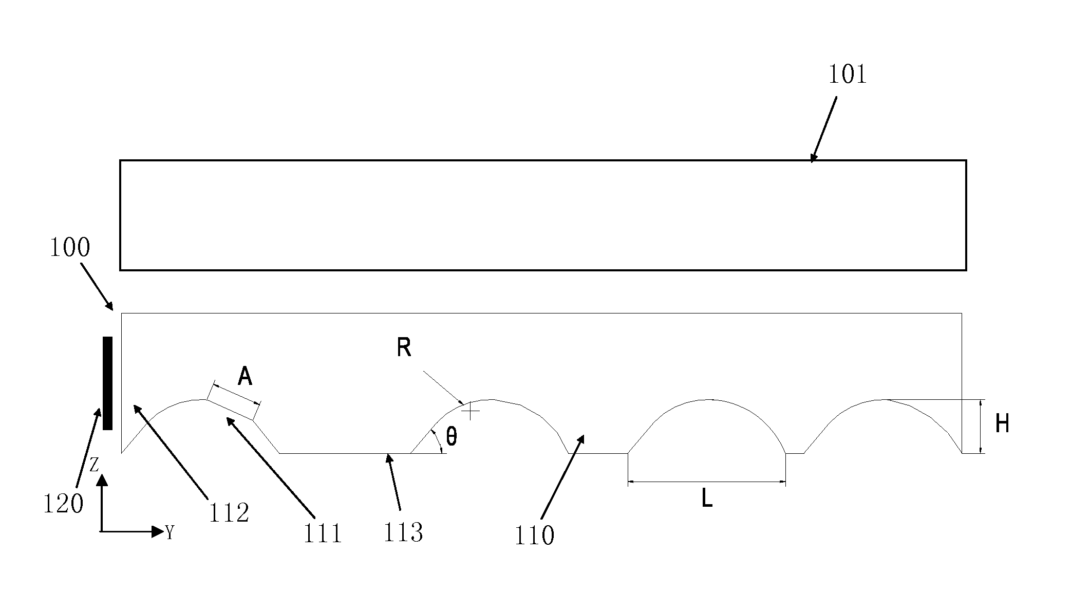
Figure 1 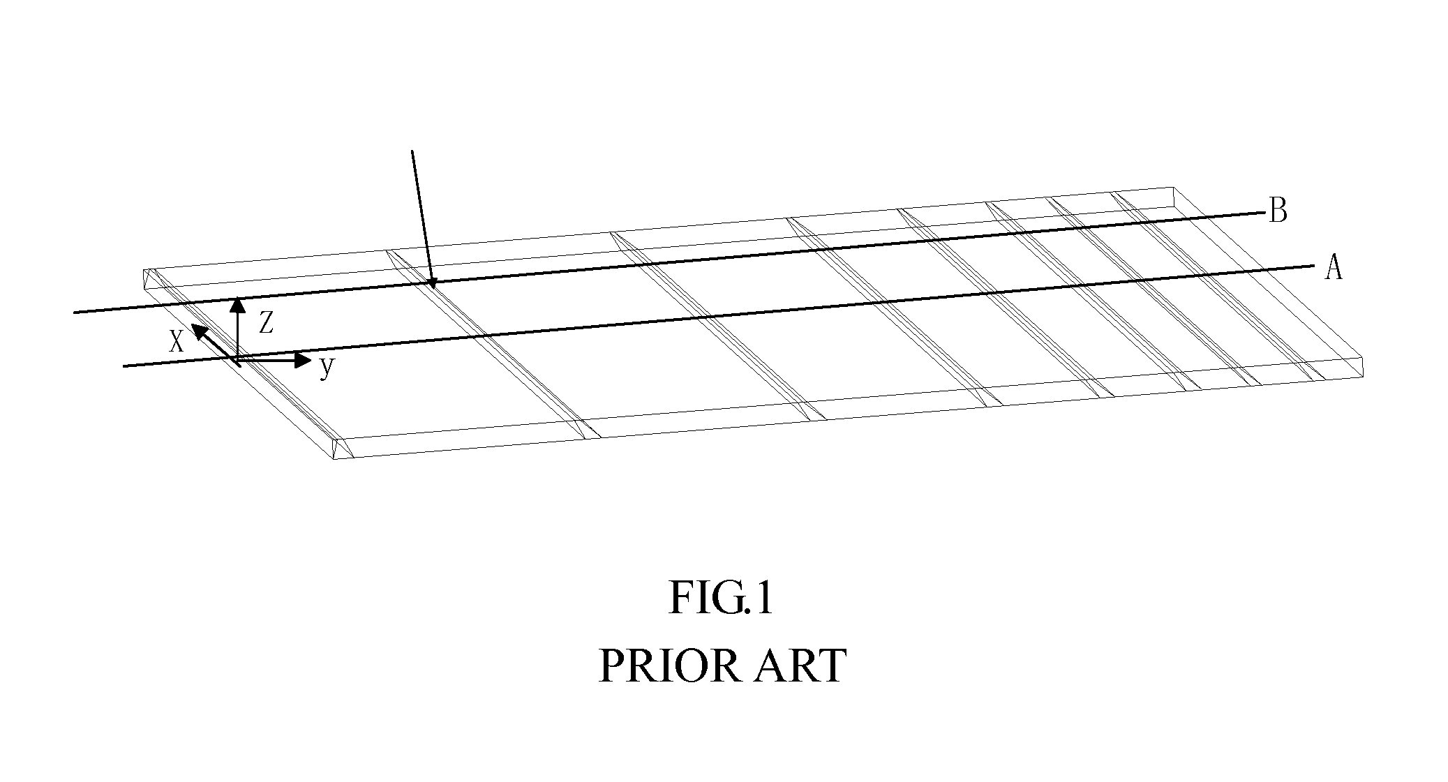
Figure 2 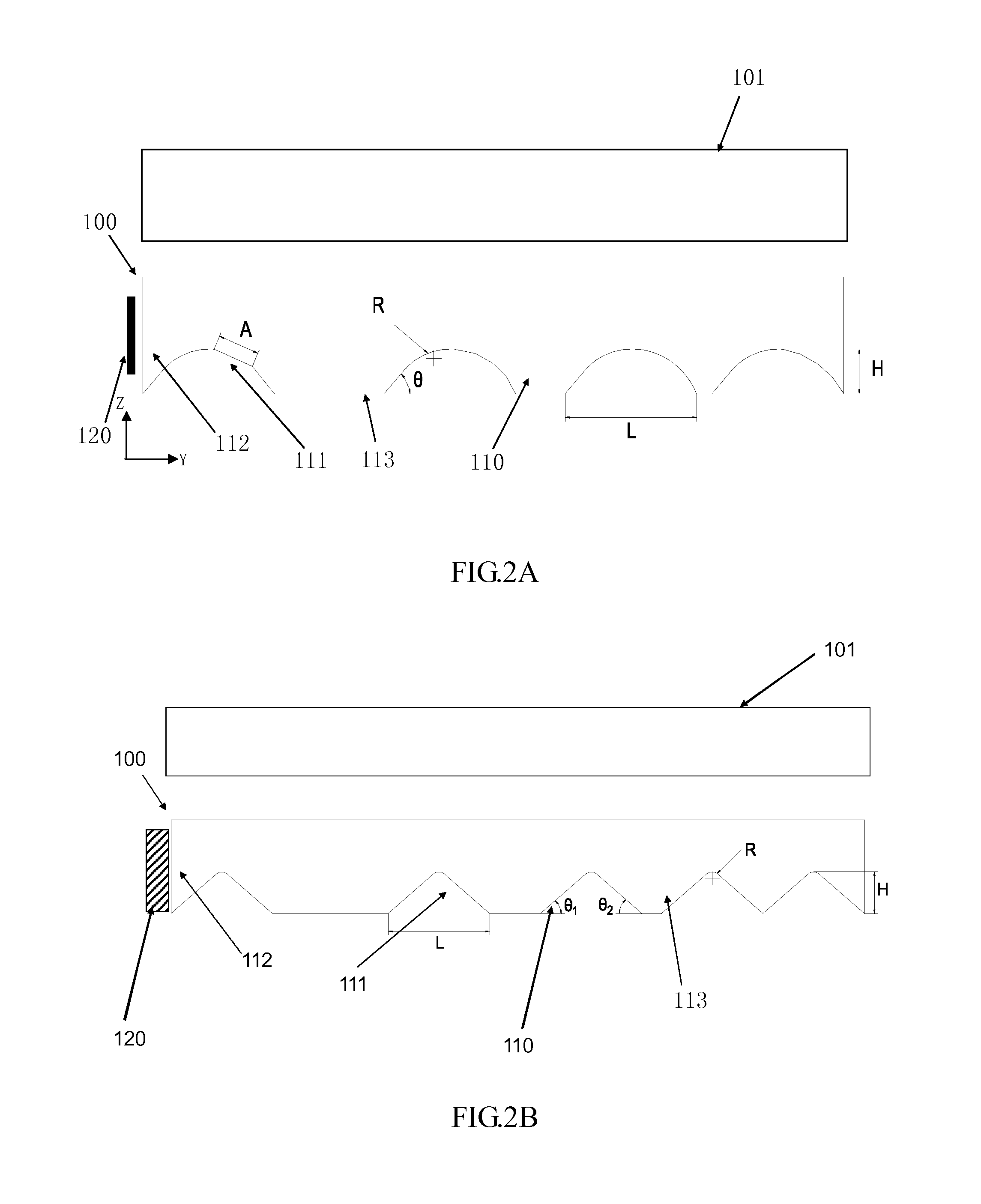
Figure 3
Abstract
Description
FIELD OF THE INVENTION
[0001] The present invention relates to a light guide plate and a backlight module, and more particularly to a light guide plate and a backlight module capable of raising luminous efficiency.BACKGROUND OF THE INVENTION
[0002] At present, for a small and thin backlight module, light emitting diodes (LEDs) are often used for lighting, wherein a light guide plate is indispensable for the backlight module.
[0003] In normal, the light guide plate has scattering patterns or microstructures. In comparison with the scattering patterns, steps and a transport cost for processing the scattering patterns are omitted with the use of the microstructures, thereby saving manufacturing cost, as well as raising a production speed of devices.
[0004] However, the light guide plate with the microstructures has the defects described as follow. For visual effects, a desirable light guide plate has a higher brightness at a middle position thereof and a lower brightness at the fringe thereof....
Examples
first embodiment
[0046]Referring to FIG. 3, a top view showing a light guide plate according to the present invention is illustrated.
[0047]In this embodiment, the profiles of the elongated microstructures 211 of the light guide plate 210 may be triangles with round corners. A curvature radius of the round corners of the profiles is altered according to the position variation in the extending direction of the elongated microstructures 211. As shown in FIG. 3, the curvature radius of the round corners of the profiles of the elongated microstructures 211 is symmetrically varied. The curvature radius (not the curvature, curvature=1 / curvature radius) of the round corners of the profiles is larger at the middle position of the elongated microstructures 211, and the curvature radius of the round corners of the profiles is less at both sides of the elongated microstructures 211, so as to make the light to be outputted from the middle position of the elongated microstructures 211 more easily, for adjusting t...
second embodiment
[0048]Referring to FIG. 6, a top view showing a light guide plate according to the present invention is illustrated.
[0049]In this embodiment, the profiles of the elongated microstructures 311 of the light guide plate 310 may be triangles. A width of the profiles of the elongated microstructures 311 is altered according to the position variation in the extending direction of the elongated microstructures 311. As shown in FIG. 6, the width of the profiles of the elongated microstructures 311 is symmetrically varied. The width of the profiles is larger at the middle position of the elongated microstructures 311, and the width of the profiles is less at both sides of the elongated microstructures 311, so as to allow the elongated microstructures 311 to reflect more light, for adjusting the brightness distribution (a higher brightness at the middle position, a lower brightness at the both sides) in the direction x. FIG. 7 is a cross-sectional diagram showing the elongated microstructures...
third embodiment
[0050]Referring to FIG. 9, a top view showing a light guide plate according to the present invention is illustrated.
[0051]In this embodiment, the profiles of the elongated microstructures 411 of the light guide plate 410 may be arcs. A curvature radius of the profiles is altered according to the position variation in the extending direction of the elongated microstructures 411. As shown in FIG. 9, the curvature radius of the profiles of the elongated microstructures 411 is symmetrically varied. The curvature radius of the profiles is less at the middle position of the elongated microstructures 411, and the curvature radius of the profiles is larger at both sides of the elongated microstructures 411, so as to make the light to be outputted from the middle position of the elongated microstructures 411 more easily, for adjusting the brightness distribution in the direction x. FIG. 10 is a cross-sectional diagram showing the elongated microstructures 411 of the light guide plate accordi...