
Evaporated fuel treatment device
a technology of evaporation fuel and treatment device, which is applied in the direction of combustion air/fuel air treatment, separation process, machines/engines, etc., can solve the problems of increased cost, increased cost, and increased cost, so as to reduce the thickness of elastic molding material, prevent the removal of the retainer member, and reduce the cost
Patent Information
- Authority / Receiving Office
- US · United States
- Patent Type
- Applications(United States)
- Current Assignee / Owner
- Publication Date
- 2013-12-12
- Estimated Expiration
- Not applicable · inactive patent
Smart Images
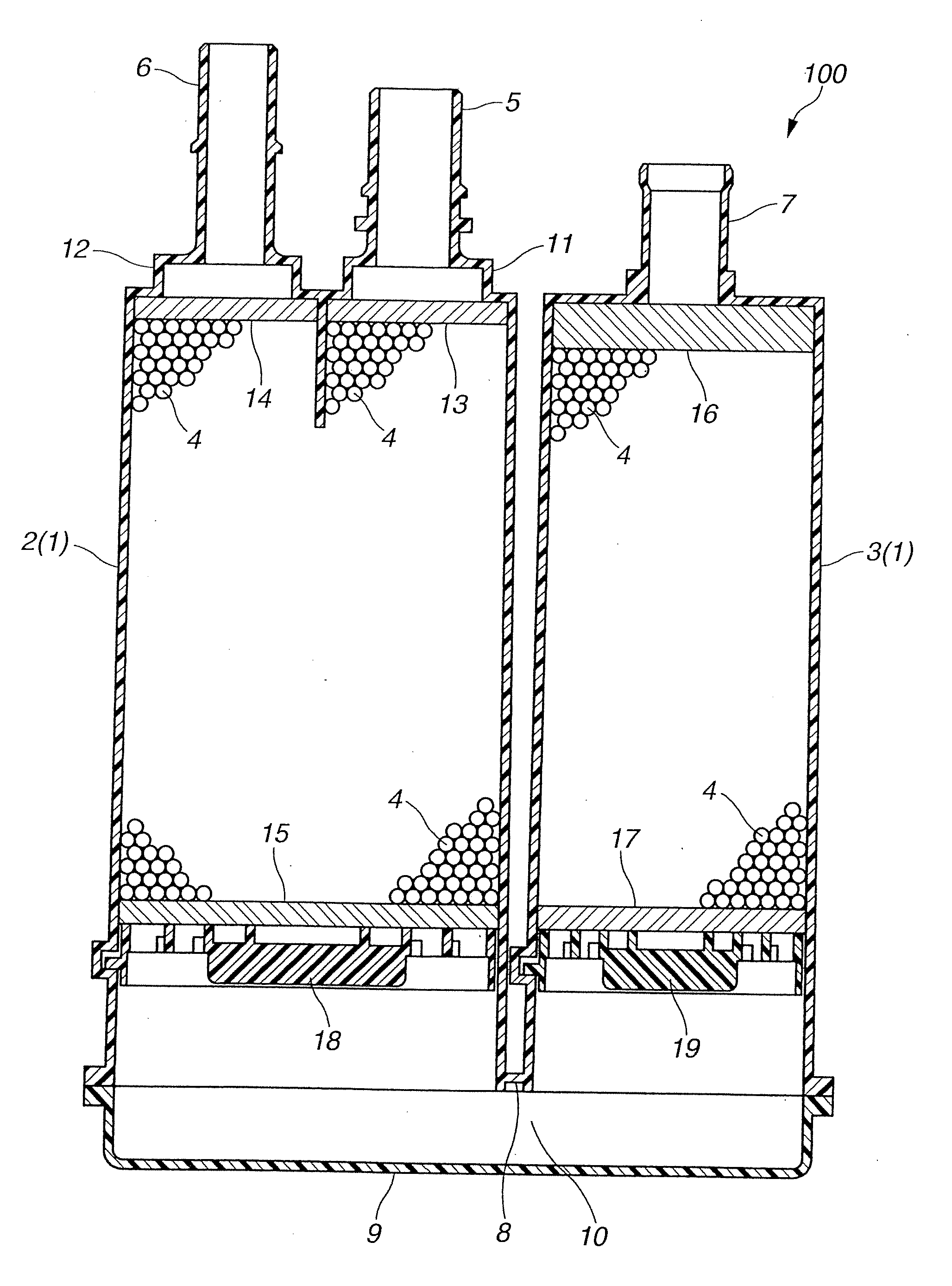
Figure 1 
Figure 2 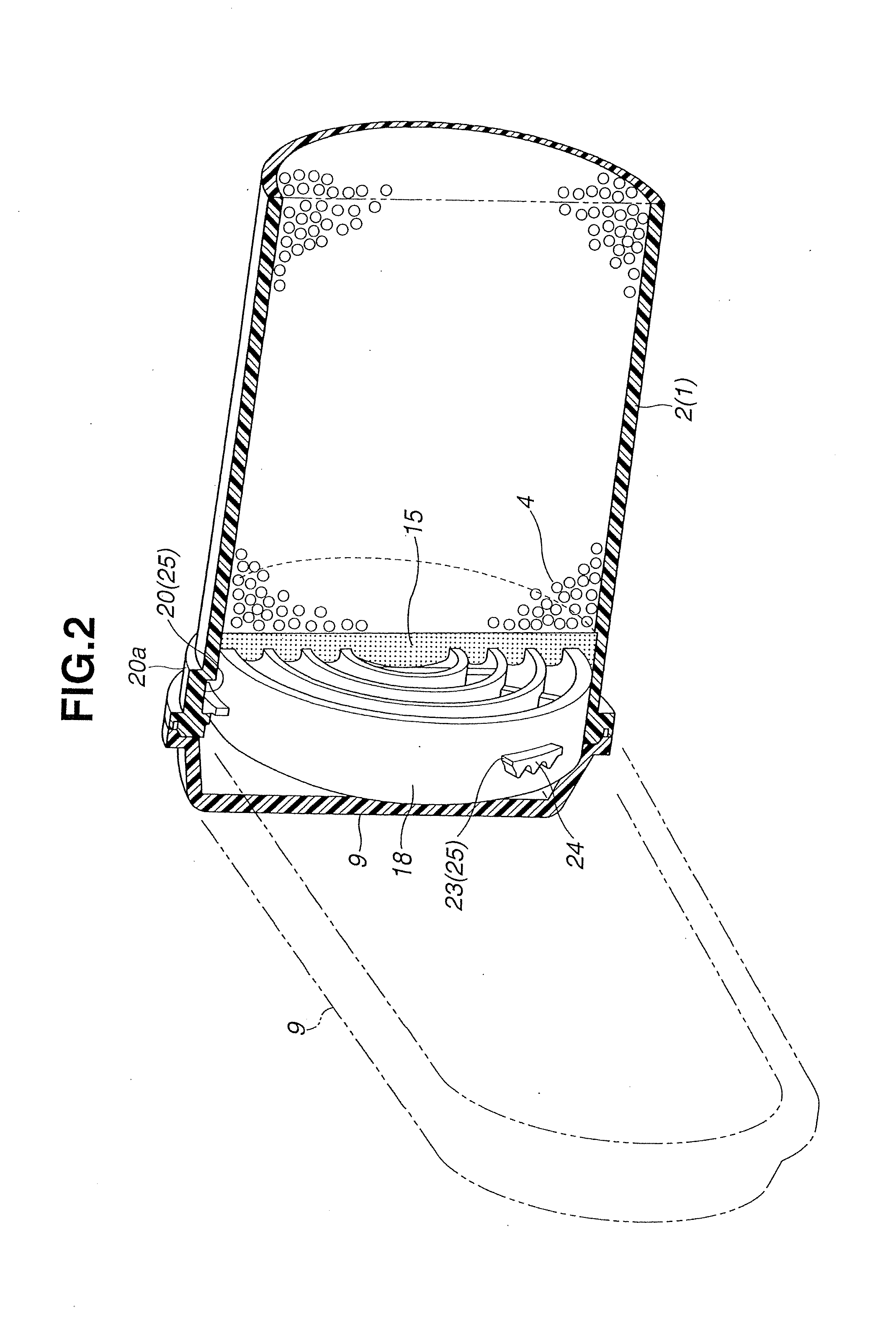
Figure 3
Abstract
Description
BACKGROUND OF THE INVENTION
[0001] The present invention relates to an evaporated fuel treatment device (also referred to as a canister) that is used for adsorbing fuel evaporated in a fuel tank of an automobile in order to allow combustion of the fuel in an engine during operation of the engine.
[0002] For example, a so-called carbon canister using activated carbon as an adsorbent is known as a conventional evaporated fuel treatment device. The canister has a flow path therein through which evaporated fuel and atmospheric air are allowed to flow. The evaporated fuel generated from the fuel tank is temporarily adsorbed in the activated carbon in the canister. On the other hand, during an operation of an engine, atmospheric air is introduced into the canister using an engine negative pressure, and the evaporated fuel adsorbed in the activated carbon is desorbed therefrom. The evaporated fuel thus desorbed is sucked into the engine, thereby serving for combustion of the evaporated fuel.[0...
Examples
first embodiment
[0035]Referring to FIG. 1 to FIG. 5, an evaporated fuel treatment device (hereinafter referred to simply as a canister) according to the present invention will be explained hereinafter. FIG. 1 shows a section of a so-called dual chamber canister as a whole. FIG. 2 to FIG. 5 show a construction of details of the canister shown in FIG. 1.
[0036]As shown in FIG. 1, a canister 100 includes a hermetically sealed casing 1, and an adsorbent 4 filled in the casing 1. The adsorbent 4 is granular activated carbon. The granular activated carbon may be generally in the form of granulated carbon particles or crushed carbon particles. The casing 1 includes a charge port 5, a purge port 6, an atmospheric vent port 7 and a cover member 9. The cover member 9 is disposed at one end of the casing 1. The charge port 5, the purge port 6 and the atmospheric vent port 7 are disposed at the other end of the casing 1.
[0037]Specifically, the casing 1 includes two cylindrical casing bodies 2, 3 made of a prede...
third embodiment
[0076]Upon assembling the canister 300 the retainer member 34 is simply pushed into the casing body 2 without being rotated. When the air permeable member 15 is brought into an appropriately compressively deformed state through the retainer member 34, the pushing force applied to the retainer member 34 is released to thereby allow meshing engagement between the tooth-shaped projecting portion 30 and the grooves and the tooth-shaped projecting portion 31. With the meshing engagement between the tooth-shaped projecting portion 30 and the tooth-shaped projecting portion 31, the retainer member 34 can be placed and held in a stepwise optional position in a direction of the pushing force. As a result, the retainer member 34 can be prevented from being removed from the casing body 2, and the air permeable member 15 can be kept in the appropriately compressively deformed state.
[0077]Accordingly, the canister 300 according to the third embodiment can attain the same effects as those of the...