

Clog resistant fluid pathway
a fluid pathway and resistance technology, applied in the field of fluid manifolds, can solve the problems of limiting the useful life of the fluid manifold and unwanted dispersion, and achieve the effect of reducing back pressure turbulence and fluid friction
Patent Information
- Authority / Receiving Office
- US · United States
- Current Assignee / Owner
- Publication Date
- 2014-05-22
- Estimated Expiration
- Not applicable · inactive patent
Smart Images
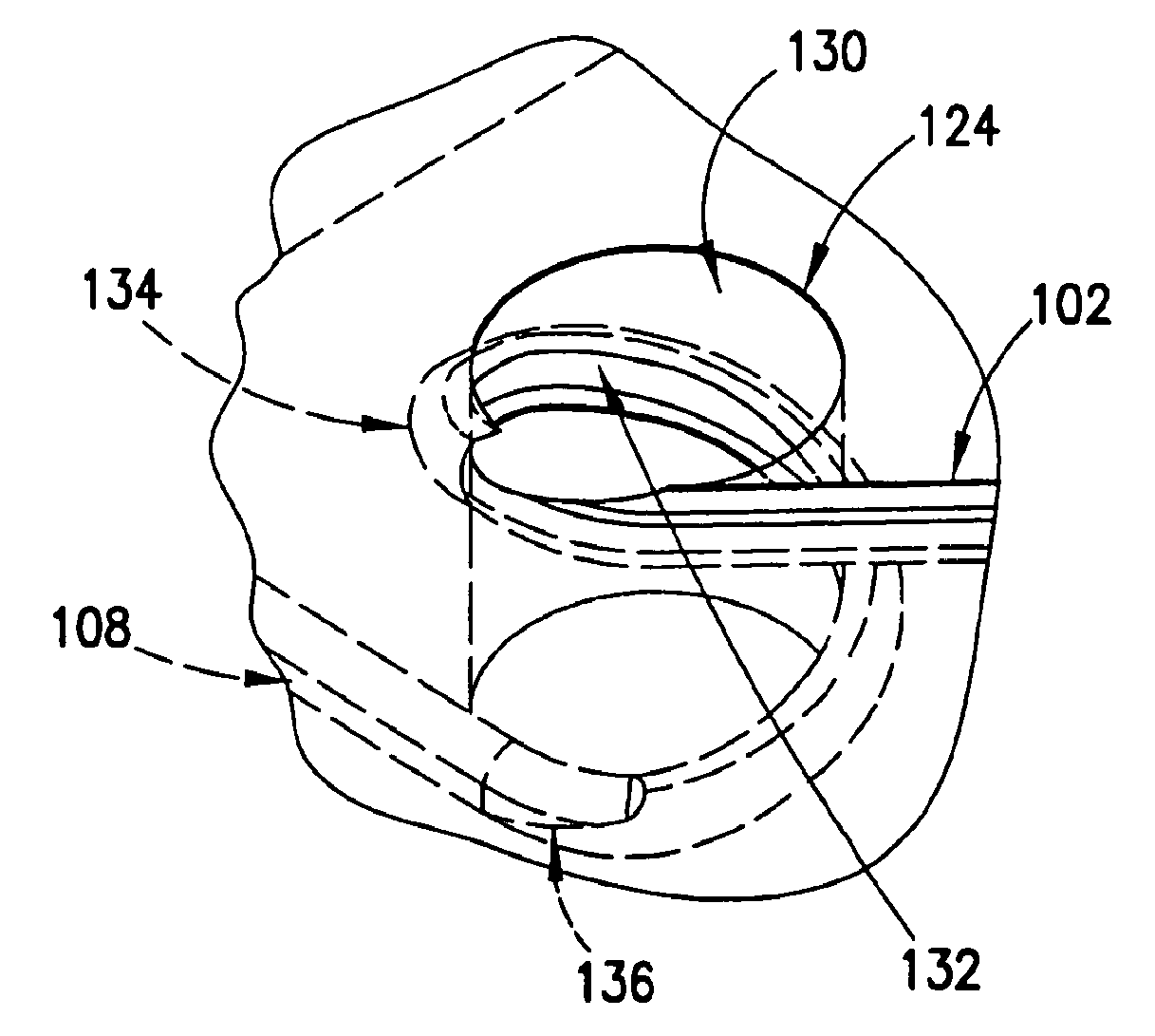
Figure 1 
Figure 2 
Figure 3
Abstract
Description
FIELD OF THE INVENTION
[0001] The present invention relates generally to fluidic manifolds and deals more particularly with fluidic passageways in such fluidic manifolds and more specifically with clog resistant leak tight smooth turn fluid pathway transitions in such fluidic passageways. The present invention also more specifically deals with fluid pathway transitions in such fluidic passageways in fluidic manifolds that are serviceable or snakeable with a fishline or other wire product to clear out potential obstructions or clogs.BACKGROUND OF THE INVENTION
[0002] Fluidic manifolds are in common use in technologies requiring control of the flow of fluids in fields such as medical equipment, analytical equipment, industrial and research equipment and the like. A fluidic manifold may be defined as having one or more inlet and outlet ports that are internally connected in a maze of passageways, channels, and cavities to conduct the flow of fluids. A fluidic manifold may be populated with...
Examples
Embodiment Construction
OF THE INVENTION
[0091]With reference to FIG. 2A a schematic diagram of a fluidic manifold having a smooth fluid transition passageway to provide a smooth clog resistant leak tight transition fluid passageway between fluid passageways on oppositely disposed major face surfaces in a layer in the fluidic manifold is shown in an example of the invention and is generally designated 100. In one example, the invention contemplates the diameter of a fluid passageway to be typically in the range of about 0.020 inches to 0.375 inches although not limited thereto and may be in the microfluidic diameter range. The fluidic manifold may be a single layer or multilayer fluidic manifold and of a material such as for example, a polymer plastic, aluminum or any other material suitable to carry out the function of the manifold. In this example, a groove or track 102 is machined or milled in the upwardly facing major face surface 104 of the layer 106 and a groove or track 108 is machined or milled in t...