

Roller for Transporting Glass Substrate and Transporting Device Thereof
Patent Information
- Authority / Receiving Office
- US · United States
- Current Assignee / Owner
- Publication Date
- 2014-10-02
- Estimated Expiration
- Not applicable · inactive patent
Smart Images
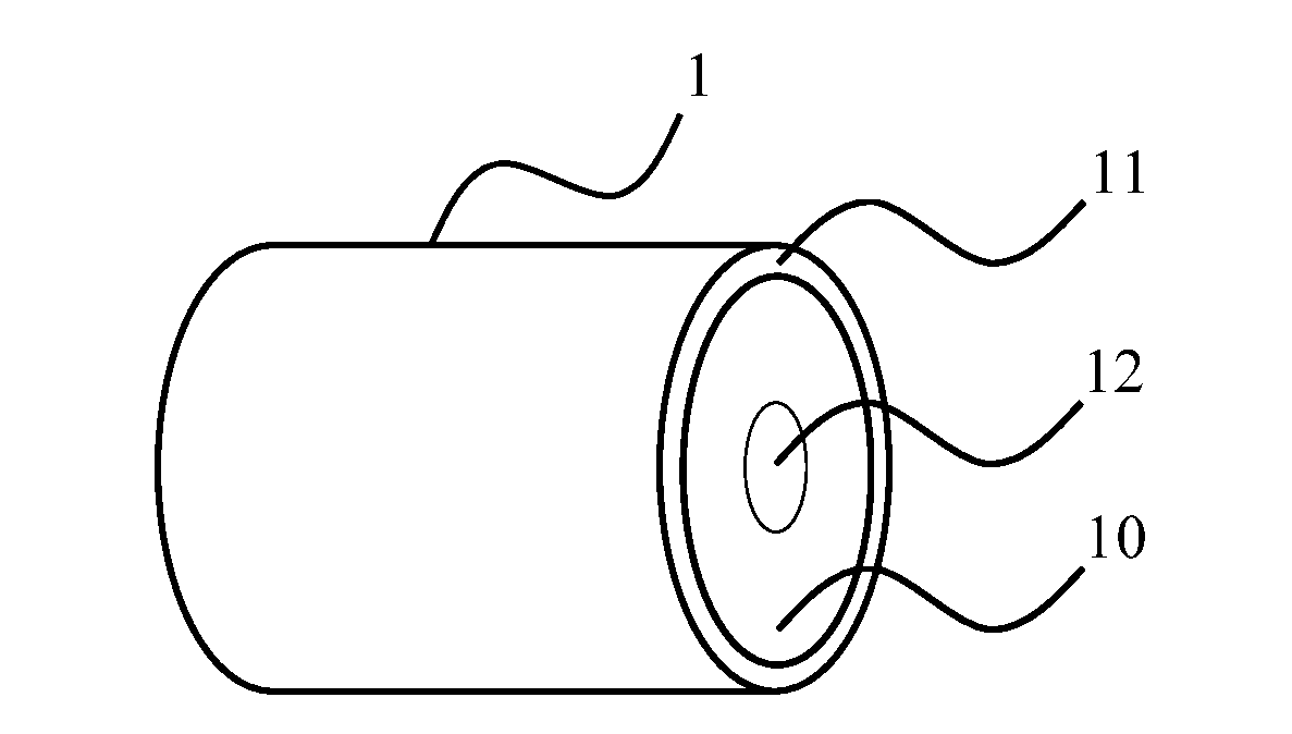
Figure 1 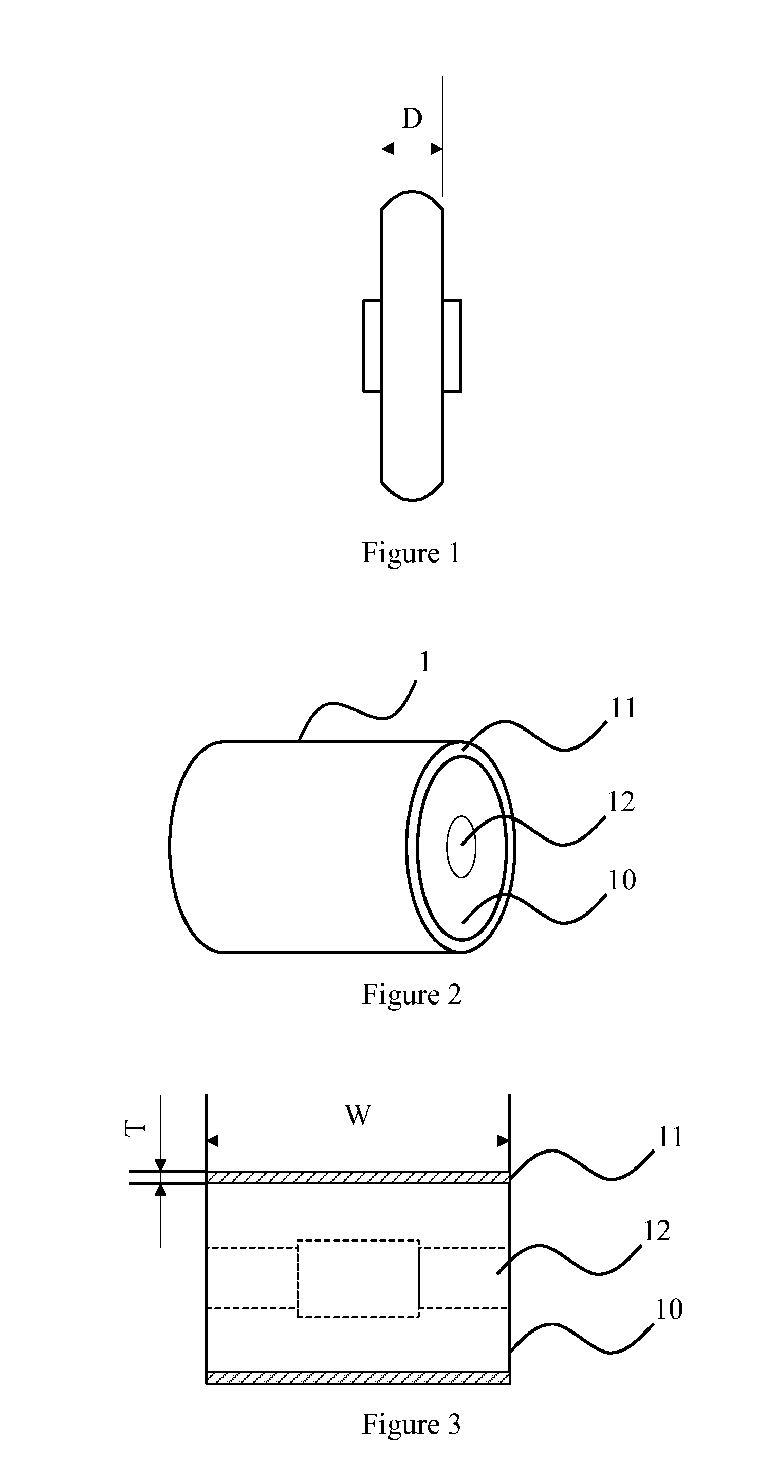
Figure 2 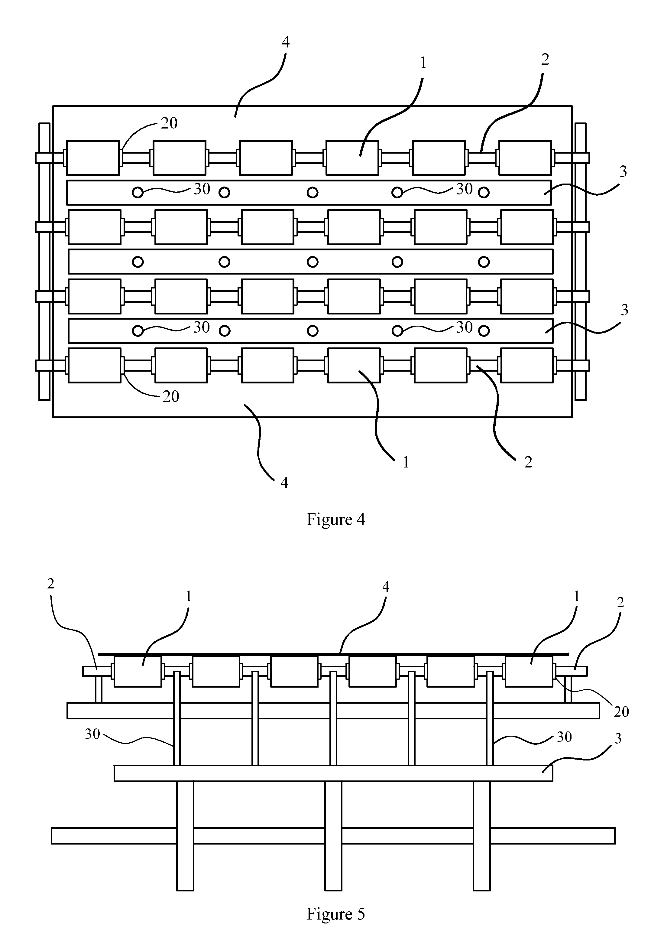
Figure 3
Abstract
Description
[0001] This application claims priority to Chinese Patent Application Serial No. 201310100770.9, named as “roller for transporting glass substrate and transporting device thereof”, filed on Mar. 26, 2013, the specification of which is incorporated herein by reference.BACKGROUND OF THE INVENTION
[0002] 1. Field of the Invention
[0003] The present invention relates to the field of image display, and in particular to a roller for transporting glass substrate and a transporting device thereof.
[0004] 2. The Related Arts
[0005] Currently, in LCD industry, there are many transporting method for glass substrate, especially roller type conveyor is the most common.
[0006] In different process sections, utilize different transporting method to deal with various purposes and requirements. For example, the roller type conveyor used in the backend of high vertical alignment (HVA) process utilizes the roller made of ultrahigh molecular weight polyethylene (UHMW-PE) with 10 mm width, which has good propertie...
Examples
Embodiment Construction
[0027]The accompanying drawings and the following detailed descriptions are the preferred embodiments of the present invention.
[0028]Referring to FIG. 2, the present invention provides a roller 1 used for transporting glass substrate, which comprises a cylindrical body 10 and an outside layer 11 coated on the side of the cylindrical body 10. The axle of the cylindrical body 10 is provided with an axle hole 12 defined through the top and the bottom, which is used to be assembled with a rotating shaft 2 (as shown in FIG. 4).
[0029]In the present invention, the width of the roller 1 is widened to 100˜120 mm. It should be noted that the body 10 of the roller 1 is cylindrical and the width of the roller 1 according to the present embodiment refers to the distance between the top and the bottom of the body 10, that is, the side length W of the cylinder as shown in FIG. 3. FIG. 3 is a sectional side view illustrating the roller 1. In the present invention, W is 100 mm, and the thickness T o...