
Method for producing a tubular compression item, and item thereby obtained
Patent Information
- Authority / Receiving Office
- US · United States
- Current Assignee / Owner
- Publication Date
- 2015-09-03
Smart Images
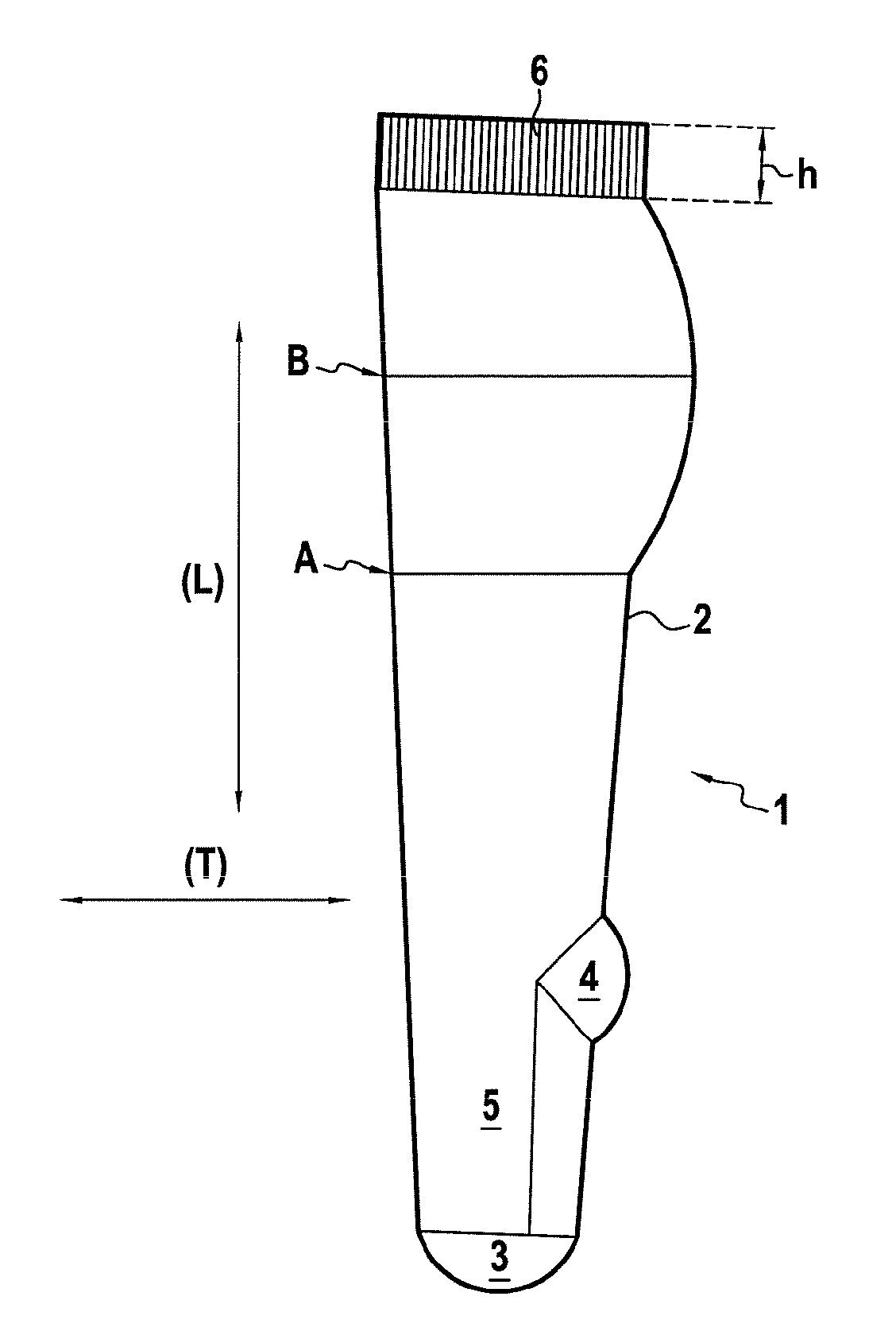
Figure 1 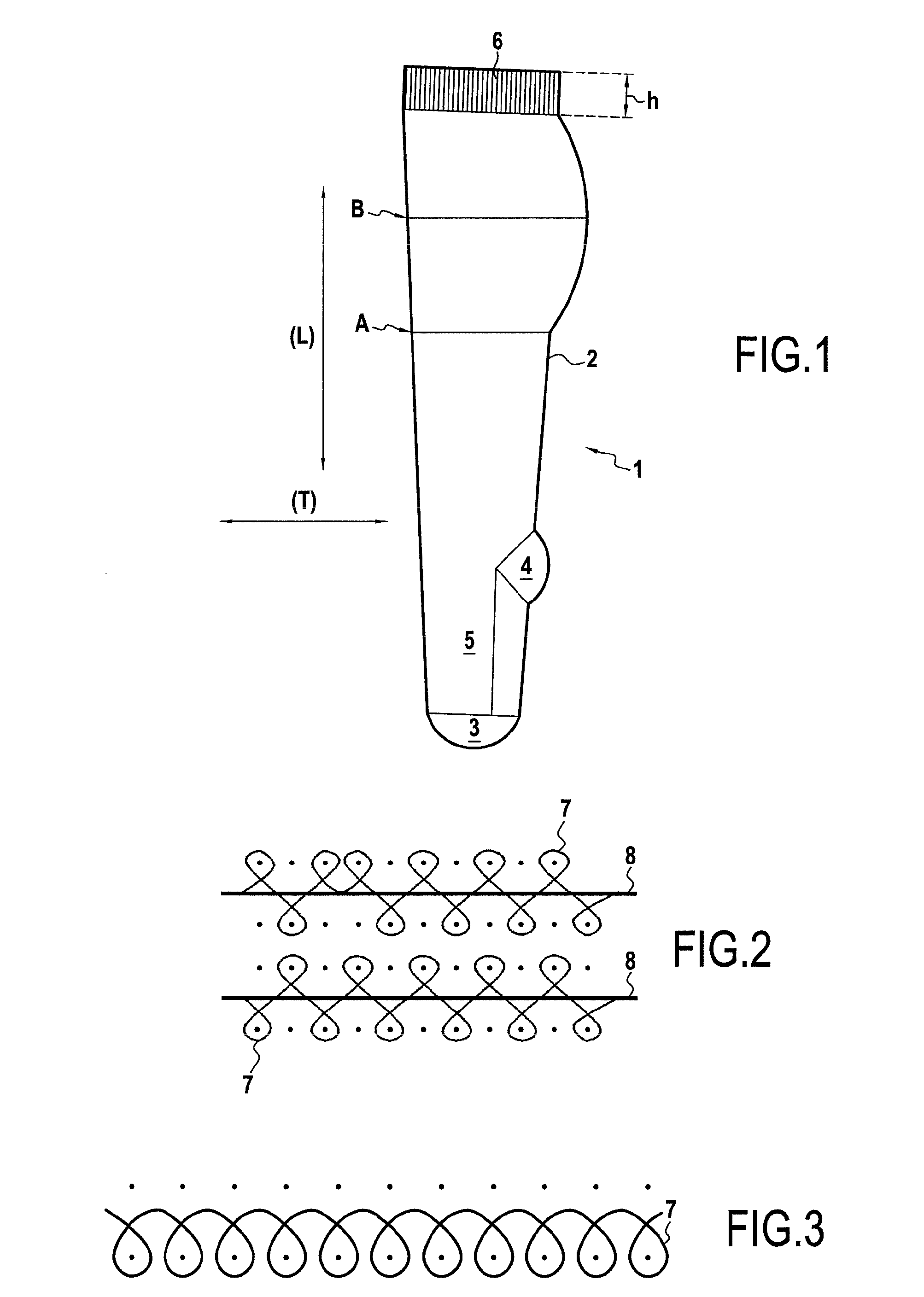
Figure 2 
Figure 3
Abstract
Description
BACKGROUND OF THE INVENTION
[0001] The present invention relates to the technical field of methods for manufacturing tubular compression items, in particular items exerting gradual compression from the ankle up to the top of the leg.
[0002] Compression items, socks or knee-length stockings, stockings, pantyhoses or further sleeves, are used for preventing or caring for venous circulation problems notably at the lower or upper limb, as well as pathologies related to malfunctions of the lymphatic system and reduction of edemas. Venous disorders may have several origins, among which are notably found: rigidification of the vein wall, alteration of the valvulae or further an increase in the diameter of the veins.
[0003] The local pressure exerted on a limb by an item with a compressive effect notably depends on the force-elongation characteristics of said item.
[0004] The pressure exerted on a limb is calculated by the following Laplace law:P [Pa or mmHg]=(T [N]×n / (L [m]×R [m]).
[0005] P represen...
Examples
Embodiment Construction
[0078]The tubular compression item 1 illustrated in FIG. 1 is a sock comprising a leg part 2, a foot tip 3, a heel 4, a foot 5 and a ribbed edge 6 in the extension of the leg part 2.
[0079]The whole of the item 1 is knitted on a twin cylinder knitting machine, i.e. comprising upper and lower superposed cylinders each working with a determined number of needles (m).
[0080]The tubular item 1 comprises a longitudinal direction (L) and a transverse direction (T) corresponding to the direction of the columns of stitches and to the direction of rows of stitches respectively.
[0081]The leg part 2, the foot 5 and the ribbed edge 6 comprise several rows of ribbed stitches respectively (n)*(p), (n′)*(p′) and (n″)*(p″) knitted with a mesh thread 7 illustrated in FIG. 2, between which are inserted elastic weft threads 8 every 1 / 1 to 1 / 5 rows of stitches. In this specific example, the elastic weft thread 8 is inserted every 1 / 1 to 1 / 2 rows of ribbed stitches (n)*(p) and (n′)*(p′), preferably betwee...