
Electronic component and method for cooling
a technology of electronic components and cooling methods, applied in the direction of electrical equipment contruction details, lighting and heating equipment, etc., can solve the problems of equipment operating at excessively high temperatures, unable to cool or at least adequate cooling,
Patent Information
- Authority / Receiving Office
- US · United States
- Patent Type
- Applications(United States)
- Current Assignee / Owner
- Publication Date
- 2019-12-19
Smart Images
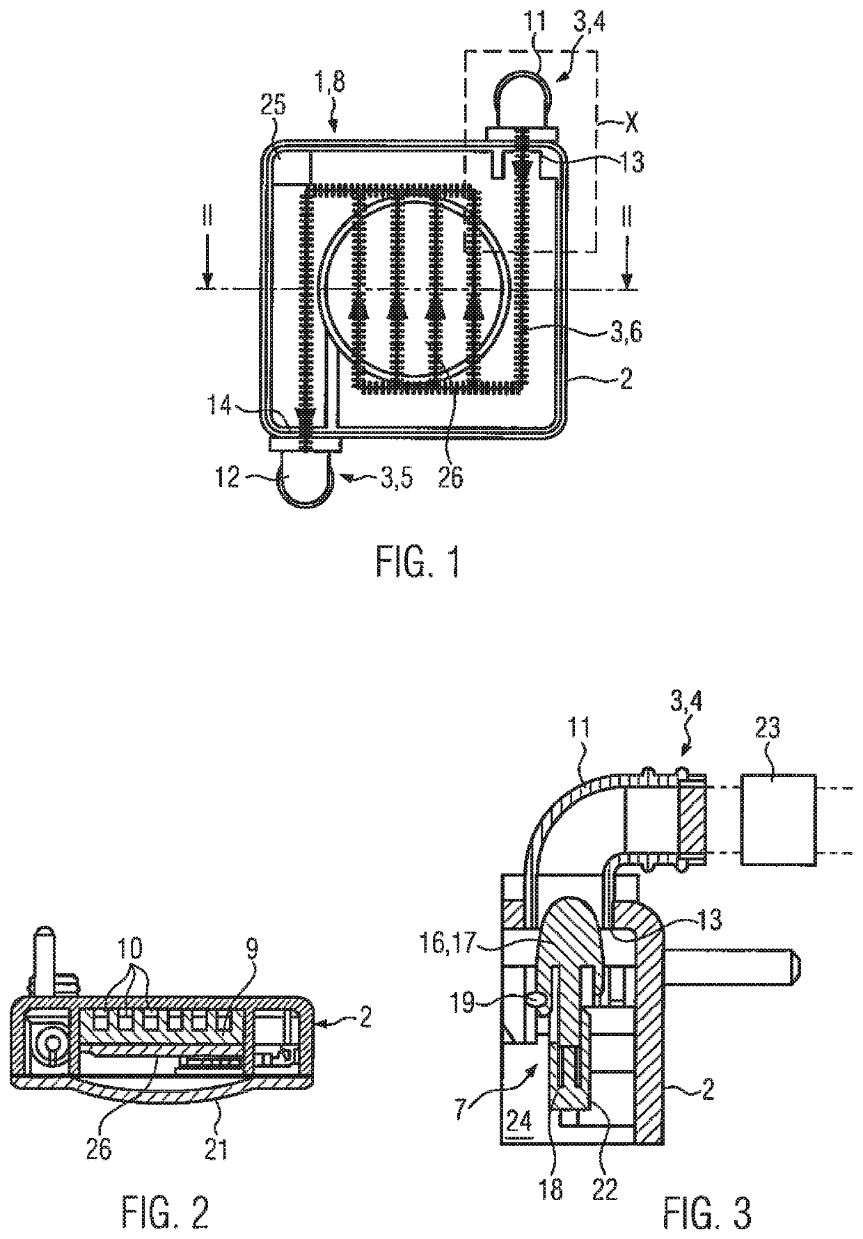
Figure 1 
Figure 2
Abstract
Description
CROSS-REFERENCE TO RELATED APPLICATIONS
[0001] This application is a National Stage Entry of, and claims priority to, PCT Patent Application No. PCT / EP2017 / 081219, filed Dec. 1, 2017, which claims priority to German Patent Application No. 102016224064.1, filed Dec. 2, 2016, both of which are hereby incorporated by reference in their entirety.FIELD OF THE DISCLOSURE
[0002] The invention relates to electrical or electronic equipment, such as a high-powered lamp, switching device, control device, transformer, signaling device, display device, or the like.BACKGROUND
[0003] Such equipment, like other compact electronic parts, generates heat which must be dissipated in order to prevent damage to the corresponding components and in particular also to increase the service life of the components. Additional requirements for such equipment, for instance, limiting the surface temperature or reliably controlling sparks in order to prevent an explosion, exist in explosion-protected areas.
[0004] In othe...
Examples
Embodiment Construction
[0047]FIG. 1 shows a plan view of an item of electrical / electronic equipment 1 according to the invention. This equipment is a high-powered lamp 8 having at least one high-powered LED 26, hereinafter referred to as H-LED. The lamp has a housing 2 which, in the illustrated view, is essentially square, although other forms of housing are also possible. The H-LED 26 is arranged inside the housing. A cooling fluid supply apparatus 3 is allocated to the H-LED 26 and in particular also to the housing 2. Of the cooling fluid supply apparatus 3, only a cooling fluid inlet apparatus 4 and a cooling fluid discharge apparatus 5 are shown in the form of pipe sockets at diagonally opposite ends of the housing. The cooling fluid inlet apparatus and cooling fluid discharge apparatus are connected outside the housing to other housings and to the rest of the cooling fluid supply apparatus 3. The cooling fluid supply apparatus 3 may also have a heat exchanger 23; see FIG. 3.
[0048]Inside the housing, ...