
Holographic security device and method of manufacture thereof
a security device and holographic technology, applied in the field of holographic security devices, can solve problems such as increased difficulty in counterfeiting
Patent Information
- Authority / Receiving Office
- US · United States
- Patent Type
- Applications(United States)
- Current Assignee / Owner
- Publication Date
- 2020-05-14
- Estimated Expiration
- Not applicable · inactive patent
Smart Images
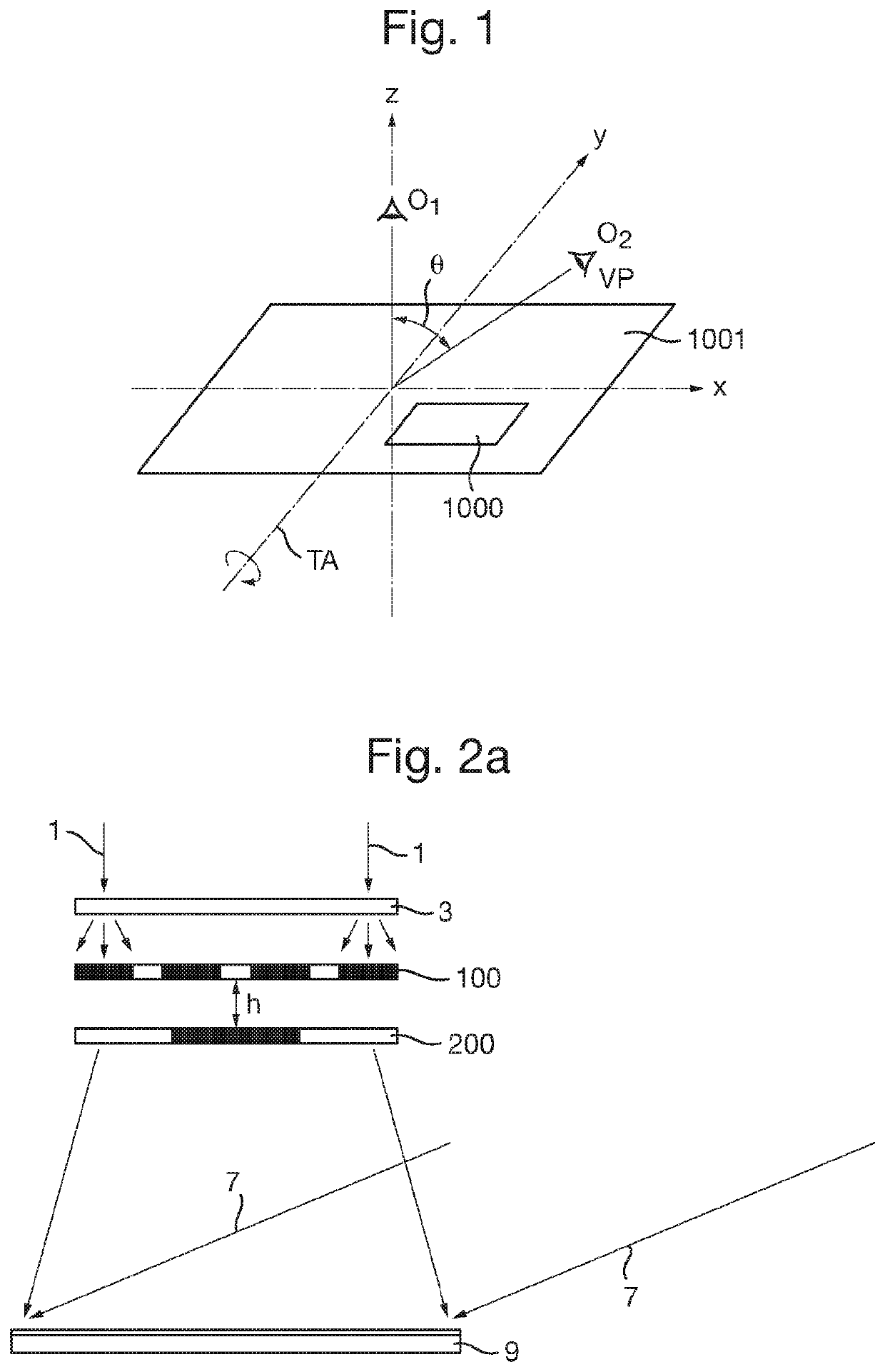
Figure 1 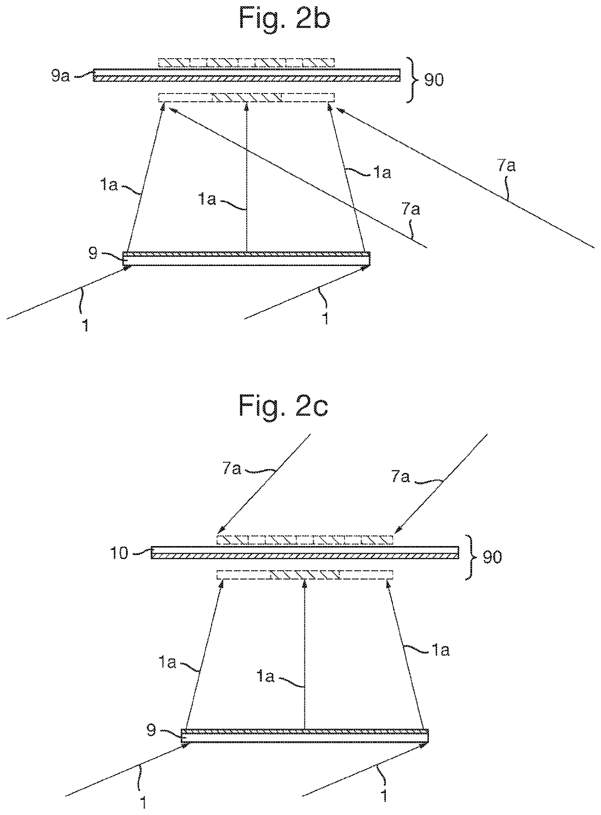
Figure 2 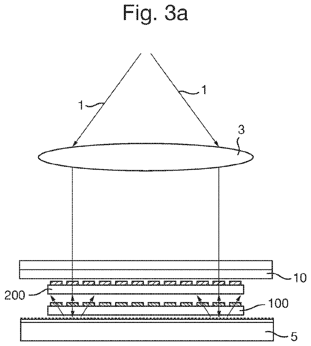
Figure 3
Abstract
Description
FIELD OF THE INVENTION
[0001] The invention relates to a holographic security device, for example for use on documents of value such as banknotes, cheques, passports, identity cards, certificates of authenticity, fiscal stamps and other secure documents. Methods of manufacturing such a security device are also disclosed.BACKGROUND TO THE INVENTION
[0002] Articles of value, and particularly documents of value such as banknotes, cheques, passports, identity cards, certificates of authenticity, fiscal stamps and other secure documents, are frequently the target of counterfeiters and persons wishing to make fraudulent copies thereof and / or changes to any data therein. Typically such documents are provided with a number of visible security devices for checking the authenticity of the object. Holographic devices are widely used as such security devices and provide an optically variable effect to an observer, meaning that the appearance of the device is different at different angles of view. H...
Examples
first example
[0135]FIG. 4a is an example sampling plate 200 and FIG. 5a is an example artwork plate 100 that may be used according to a first example of the invention in order to provide a phase interference effect. The sampling plate 200 illustrated in FIG. 4a (with a magnified view shown in FIG. 4b) comprises a regular array of substantially opaque rectangular elements 201 having their long axes directed along the Y axis. The rectangular elements 201 are separated along a direction perpendicular to their long axes (i.e. separated along the X axis). The rectangular elements 201 are substantially opaque, with the gaps 202 between the rectangles being substantially transparent to visible light such that light from the artwork plate can pass through. In this example each rectangular element 201 has a width of 600 μm and the rectangular elements are separated by gaps 202 of 100 μm.
[0136]The artwork plate 100 illustrated in FIG. 5a comprises two spaced apart star-shaped indicia 101a, 101b, with FIG....
second example
[0139]FIG. 7 illustrates an alternative artwork plate 110 that may be used with the sampling plate 200 described above. Again, the exhibited effect will be a phase interference effect. Artwork plate 110 comprises two arrays 111, 112 of overlapping circles arranged in a curved manner. Array 111 comprises circles 111a, 111b . . . 111g and array 112 comprises circles 112a, 112b . . . 112g. Each circle is comprised of an array of vertical segments (directed along the Y axis), with the arrays of each circle being offset from each other such that at a particular viewing angle of the resulting hologram, only one circle of each array 111, 112 is visible. This exhibits an animation effect with the circles appearing to change in position and size upon tilting of the hologram about the Y axis, as schematically illustrated in FIG. 8. As before, this arrangement of artwork and sampling plates generates seven frames seen at viewing angles Θ1 to Θ7. Under diffuse light, this effect is minimised an...
third example
[0140]FIG. 9a illustrates an artwork plate 120 that may be used with sampling plate 210 (illustrated in FIG. 10a) in order to produce a striking “contrast switch” phase interference effect that is illustrated in FIGS. 11a and 11b. As seen in FIG. 11a, at a first viewing angle Θ1 of the device 100, a first pattern of indicia is exhibited. More specifically, a shaded “5” symbol 121 is displayed against a light background, a shaded region 123 outlines a light “£” symbol 122, and two star shapes 124, 125 are exhibited. At a second viewing angle of the device, Θ2 (e.g. tilting the device about the Y axis), the same symbols are exhibited but the light and shade are reversed.
[0141]In contrast to the first and second embodiments, only two frames are visible here, as the sampling plate 210 comprises an array of substantially opaque rectangular elements 211 (see FIG. 10b) that are spaced apart by a distance equal to the width of each rectangular element. In other words, the substantially tran...