
Fuel supply for direct injected engine
Patent Information
- Authority / Receiving Office
- US · United States
- Current Assignee / Owner
- Publication Date
- 2001-04-10
- Estimated Expiration
- Not applicable · inactive patent
Smart Images
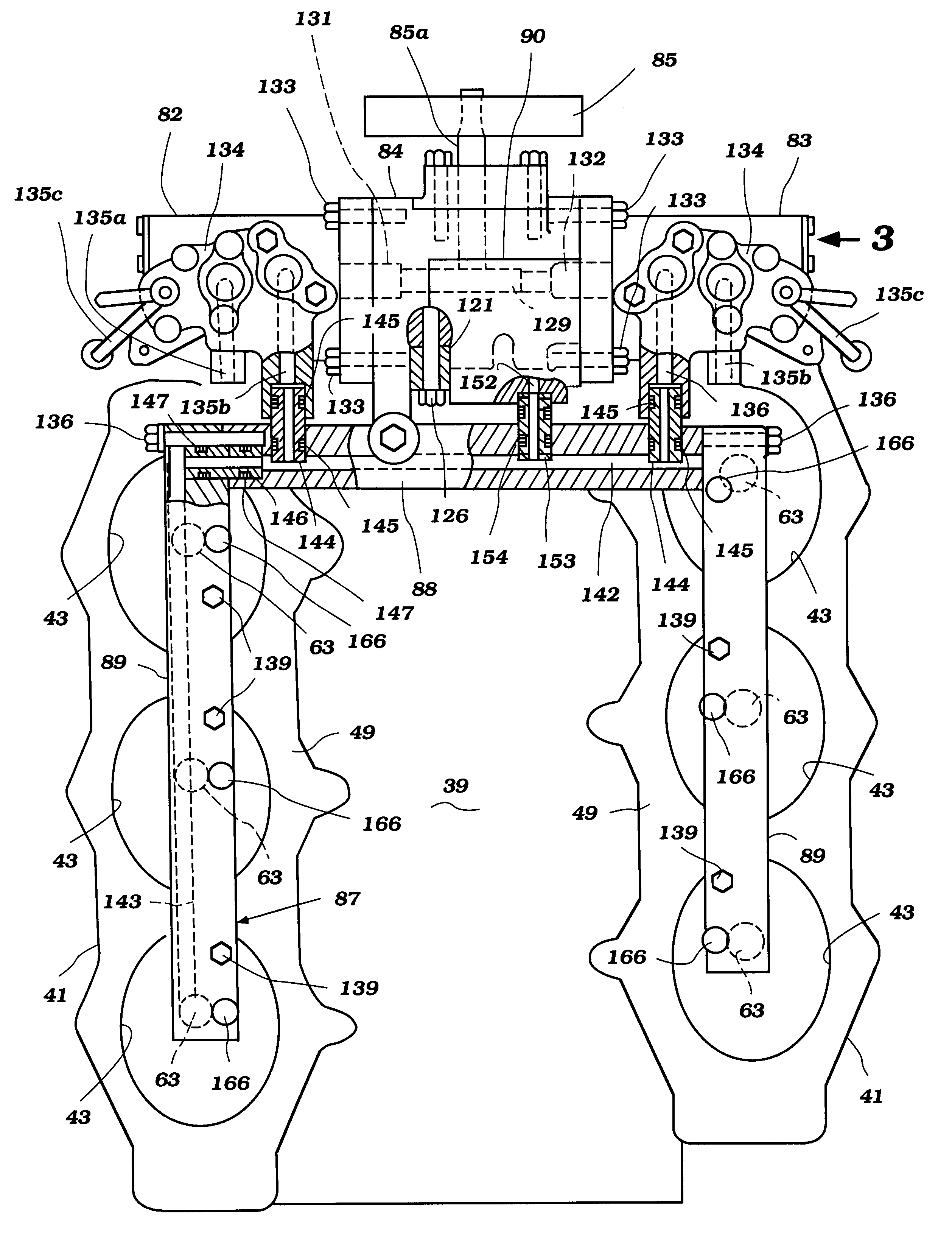
Figure 1 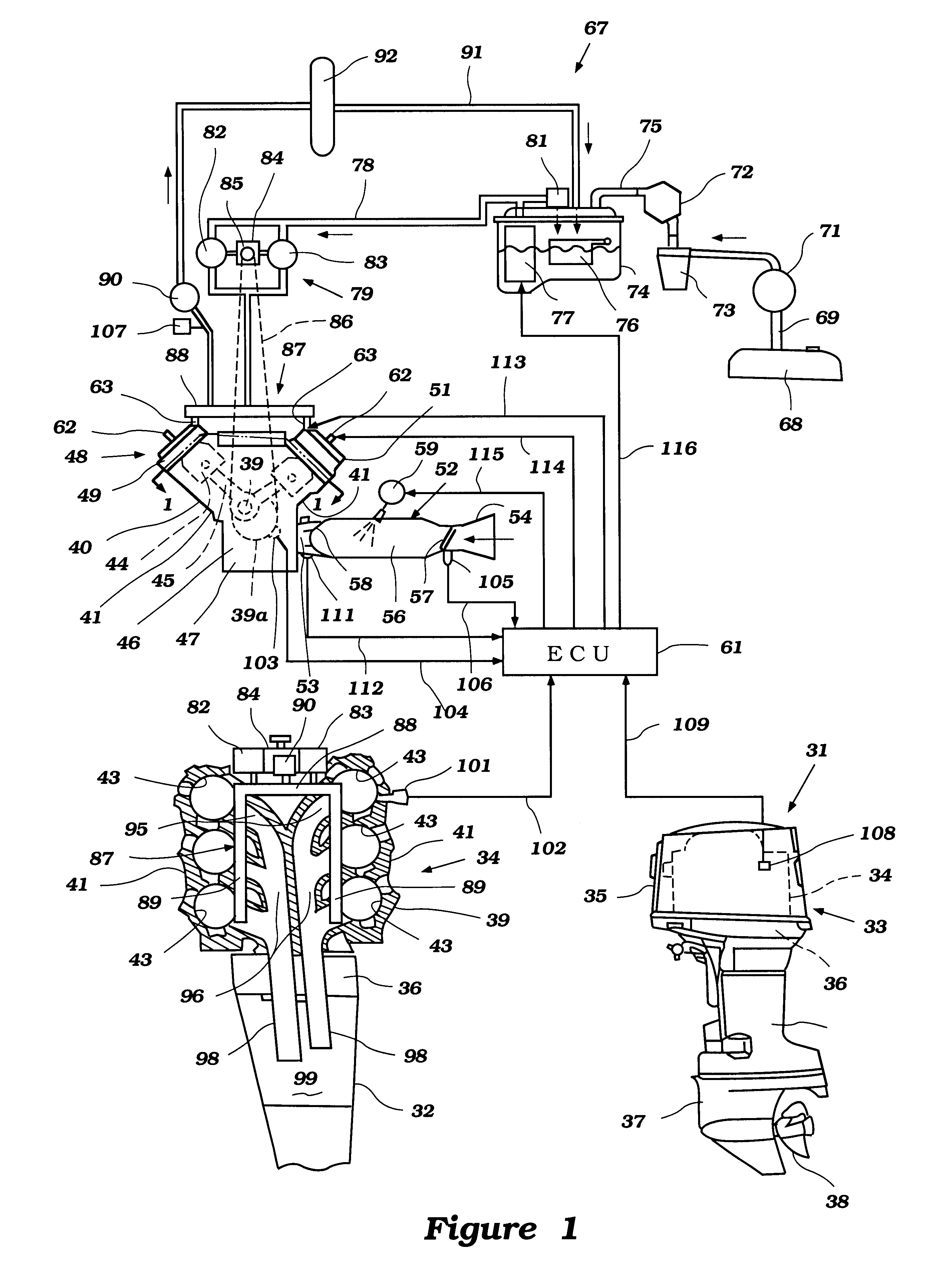
Figure 2 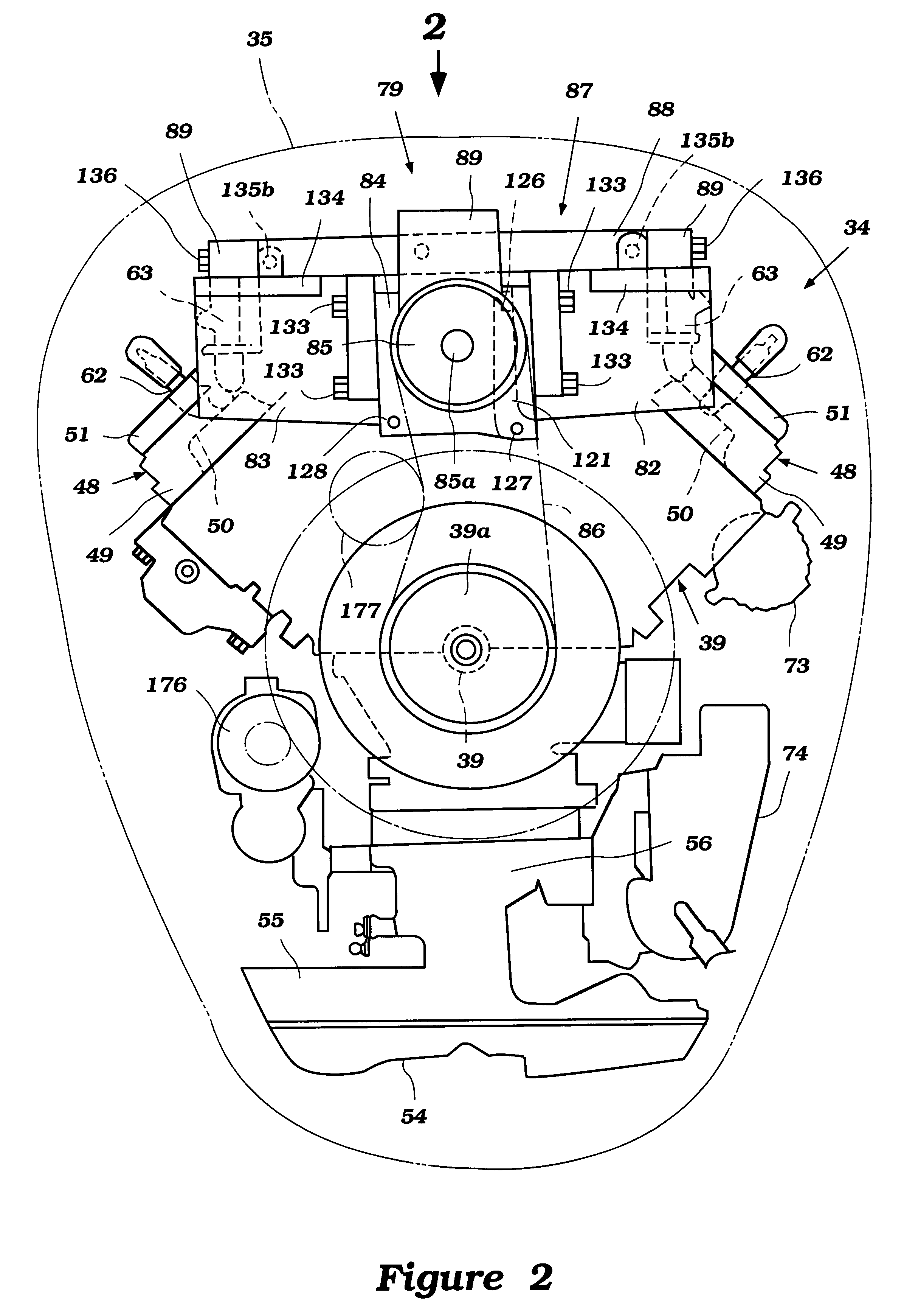
Figure 3
Abstract
Description
1. Field of the InventionThis invention relates to a fuel injected system for a direct injected engine and more particularly to an improved fuel supply arrangement for an outboard motor incorporating a direct injected system.2. Description of Related ArtAs is well known, in all fields of engine design there is an increasing emphasis on obtaining more effective emission control, better fuel economy and, at the same time, continued high or higher power output. This trend has resulted in the substitution of fuel injection systems for carburetors as the engine charge former. In the common systems used, fuel is injected into an intake air manifold. In order to obtain still further improvement, direct injection systems are being considered. These systems inject fuel directly into the combustion chamber and thus have significant potential advantages.This direct injection, however, means that the pressure into which the fuel is injected is higher than with manifold injection systems wherein...
Examples
Embodiment Construction
The general overall environment in which the invention is practiced and certain details of the engines will be described primarily by reference to FIG. 1 and additionally to FIGS. 2 through 7.
In the lower-right hand view of the FIG. 1, an outboard motor constructed and operated in accordance with an embodiment of the invention is depicted in side elevational view and is identified generally by the reference numeral 31.
The entire outboard motor 31 is not depicted in that the swivel bracket and clamping bracket that are associated with the driveshaft housing, indicated generally by the reference numeral 32, are not illustrated. This is because these components are well known in the art and the specific method by which the outboard motor 31 is mounted to the transom of an associated watercraft is not necessary to permit those skilled in the art to understand or practice the invention.
The outboard motor 31 includes a power head, indicated generally by the reference numeral 33, that is p...