
Method of reducing pressure peaks in a fuel injector
a fuel injector and pressure peak technology, which is applied in the direction of fuel injecting pumps, machines/engines, positive displacement liquid engines, etc., can solve the problems of variable pump systems that are not currently or widely used in the automotive industry, the displacement of hydraulic pumps is not adjusted to the needed amount of energy, and the injection variation is not widely used. , to achieve the effect of increasing fuel efficiency
Patent Information
- Authority / Receiving Office
- US · United States
- Patent Type
- Patents(United States)
- Current Assignee / Owner
- Publication Date
- 2005-03-22
- Estimated Expiration
- Not applicable · inactive patent
Smart Images
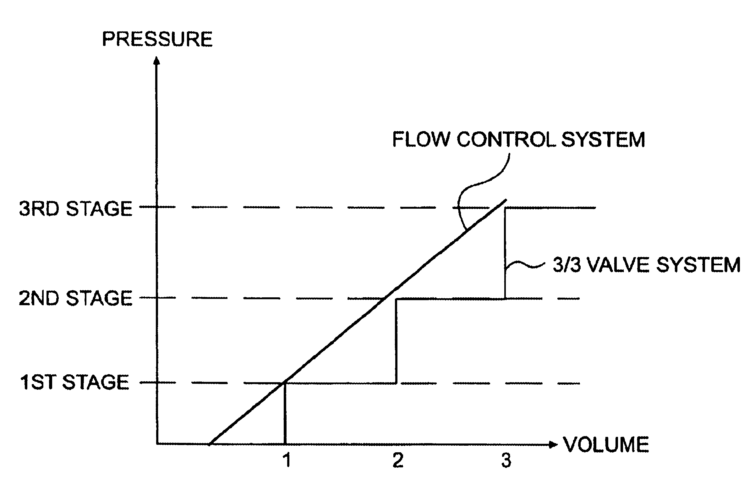
Figure 1 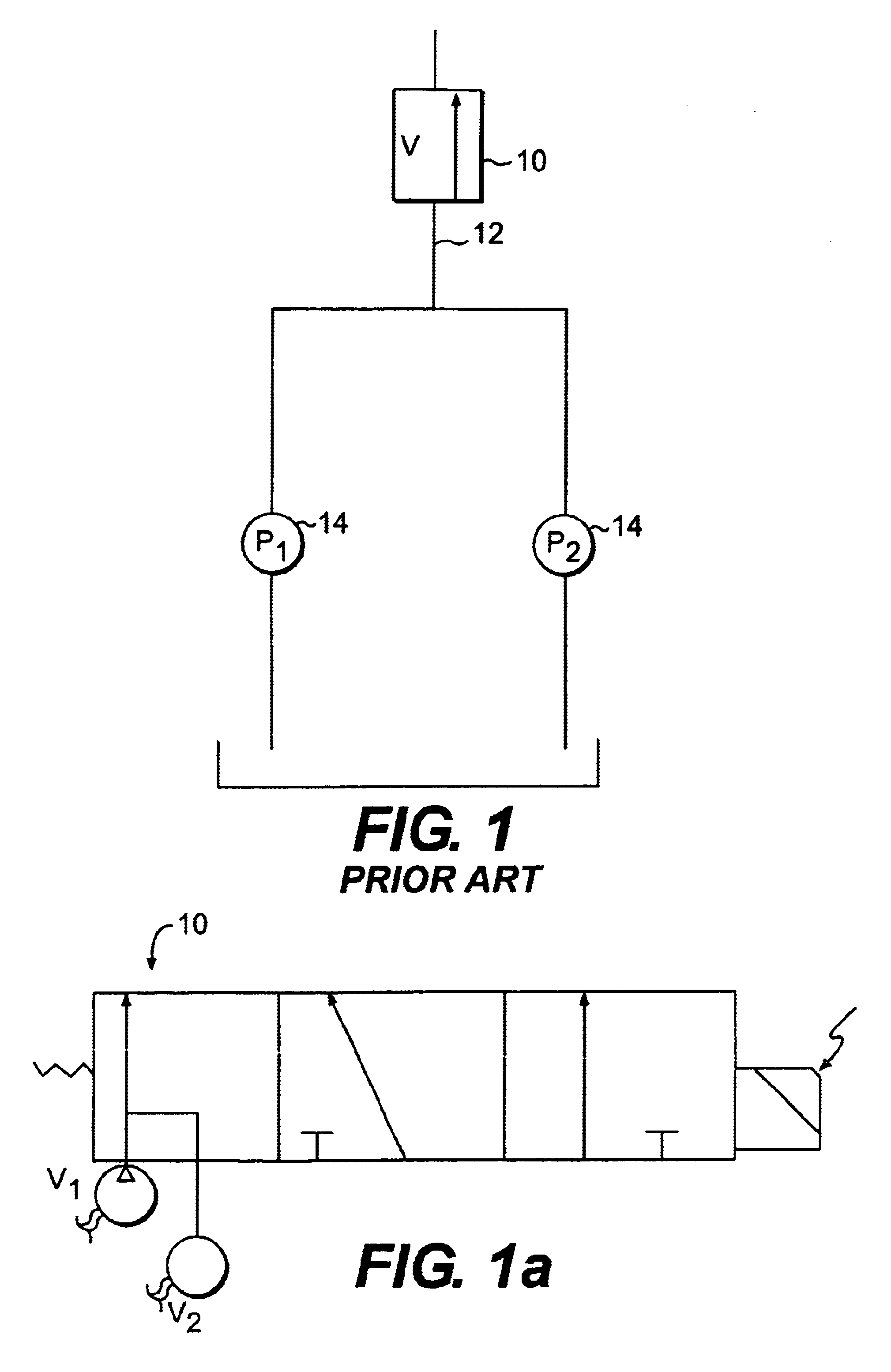
Figure 2 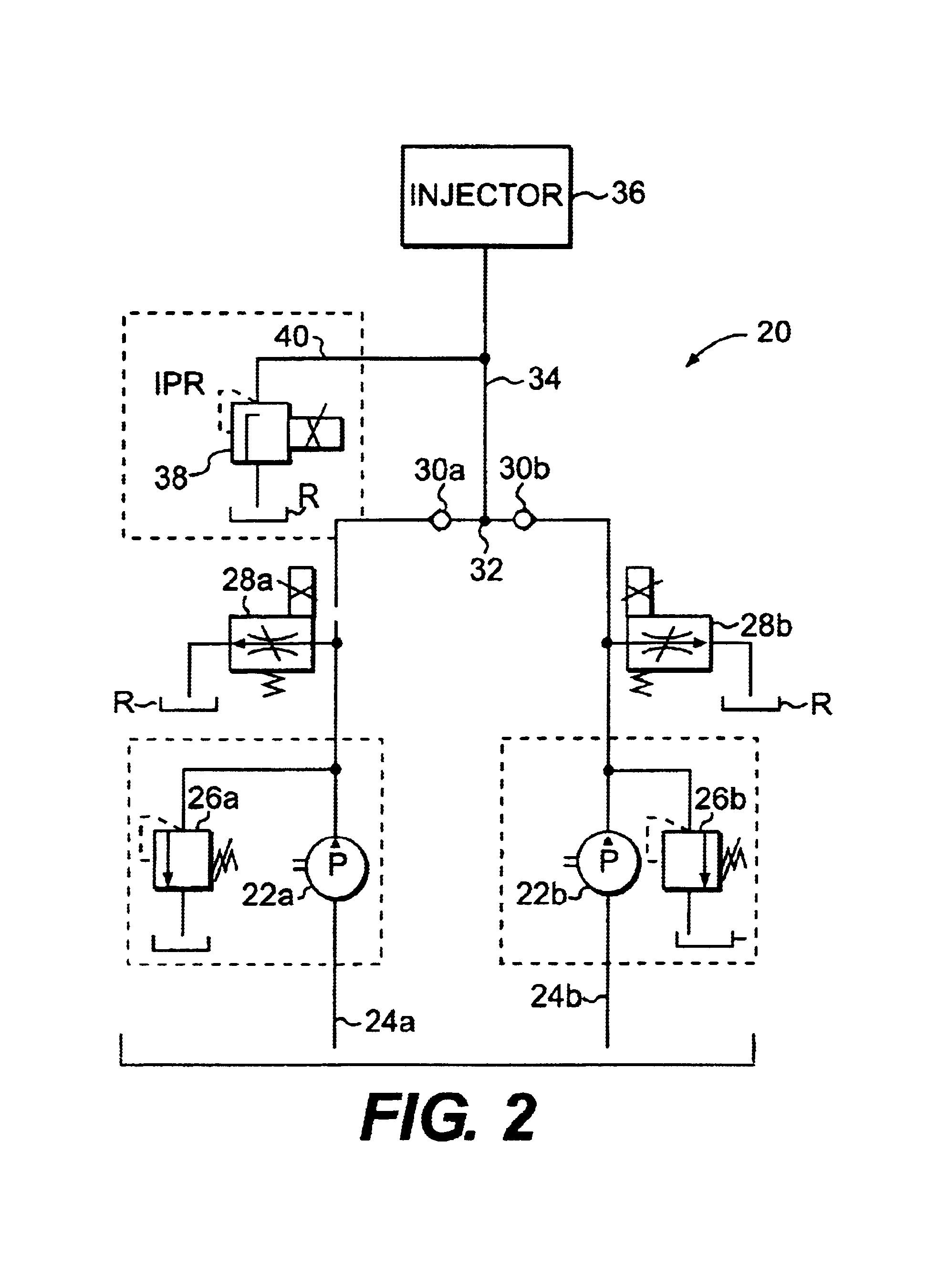
Figure 3
Abstract
Description
CROSS REFERENCE TO RELATED APPLCIATIONS
[0002] This application is a divisional application of and claims priority to copending U.S. application Ser. No. 10 / 079,489 filed Feb. 22, 2002, which incorporated herein in its entirety.
[0003] The present application claims priority to U.S. provisional application Ser. No. 60 / 283,629, filed on Apr. 16, 2001, the entire disclosure which is incorporated herein by reference.BACKGROUND OF THE INVENTION
[0004] 1. Field of the Invention
[0005] The present invention generally relates to a multiple stage pump and, more particularly, to a variable displacement multiple stage pump for a hydraulic system.
[0006] 2. Background Description
[0007] Hydraulic pumps are widely used in a vast array of automotive and heavy machinery applications. These applications may include, for example, drive vehicles, powerful hydraulic cylinders and injection systems. In current systems, pump displacement of the hydraulic pump is not adjusted to the needed amount of energy for a de...
Examples
Embodiment Construction
s, aspects and advantages will be better understood from the following detailed description of a preferred embodiment of the invention with reference to the drawings, in which:
[0021]FIG. 1 shows a conventional multistage pump with a control valve on a common rail;
[0022]FIG. 1a shows an exploded view of a 3 way / 3 position valve used with the system of FIG. 1;
[0023]FIG. 2 shows a first embodiment of the multiple stage pump of the present invention utilizing a pressure valve;
[0024]FIG. 3 shows another embodiment of the multiple stage pump of the present invention utilizing a flow valve;
[0025]FIG. 4 shows another embodiment of the multiple stage pump of the present invention utilizing a flow valve with a flow closed loop control; and
[0026]FIG. 5 shows a performance graph using the multiple stage pump of the present invention.
DETAILED DESCRIPTION OF A PREFERRED EMBODIMENT OF THE INVENTION
[0027]The present invention is directed to a multiple stage pump for hydraulic systems, and more part...