
Twist fitting for air tank connections
Patent Information
- Authority / Receiving Office
- US · United States
- Current Assignee / Owner
- Publication Date
- 2005-09-13
- Estimated Expiration
- Not applicable · inactive patent
Smart Images
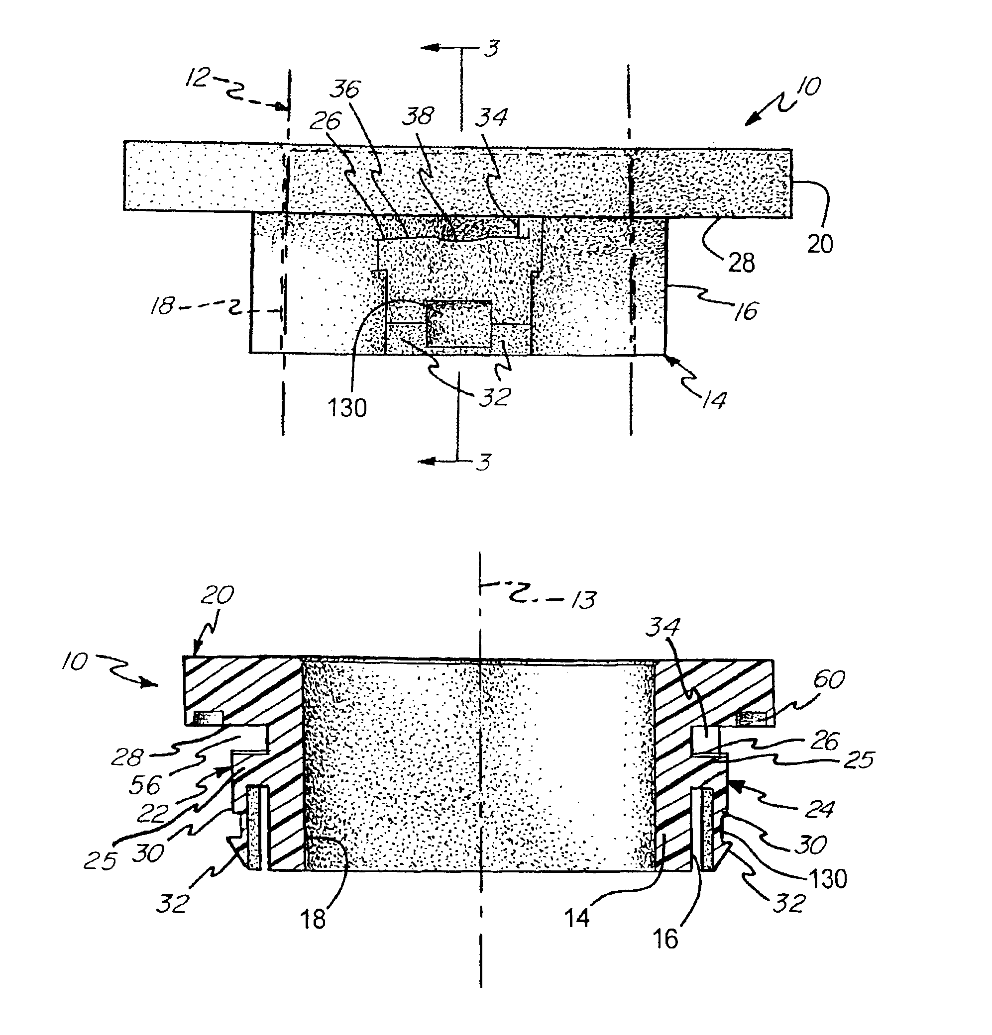
Figure 1 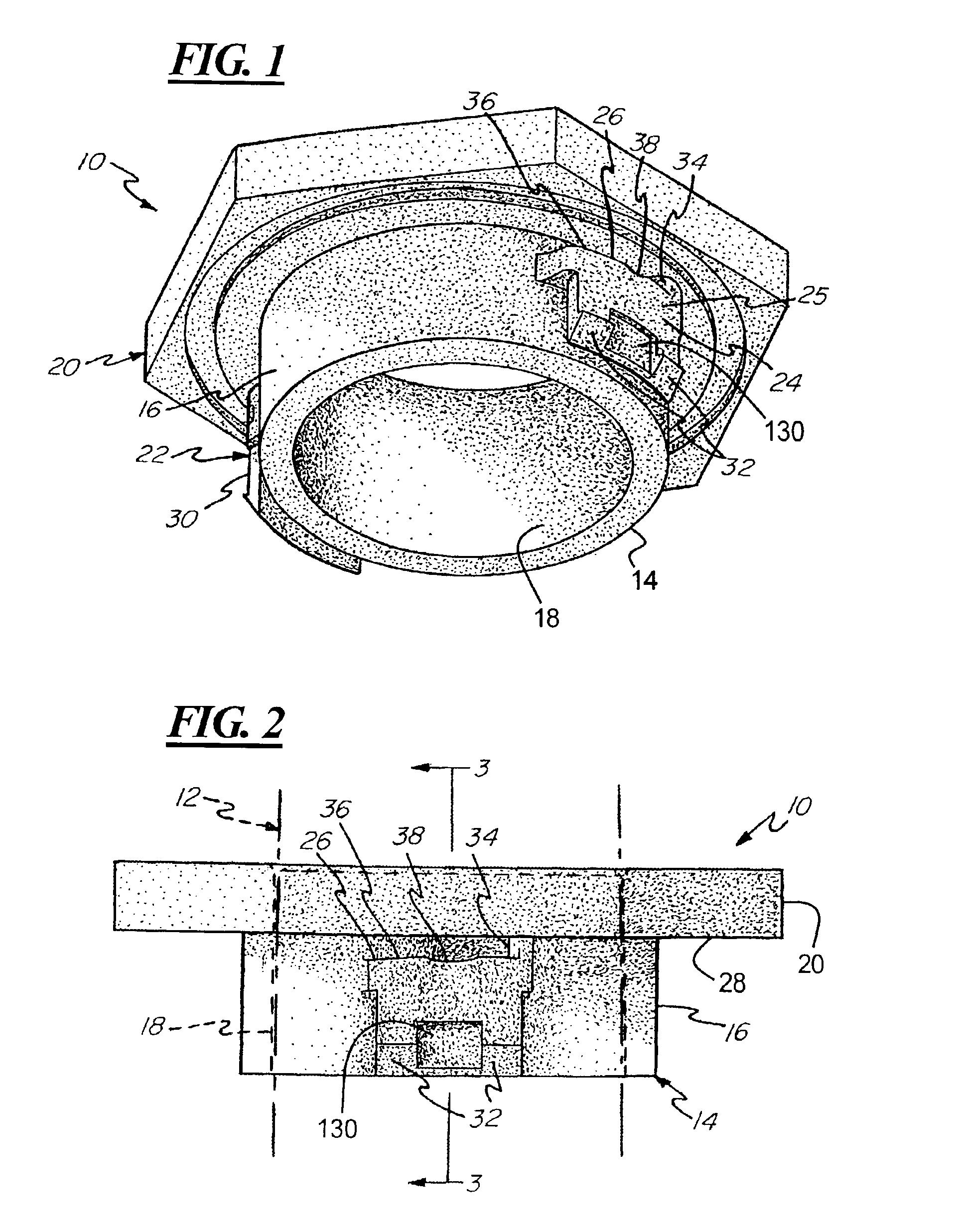
Figure 2 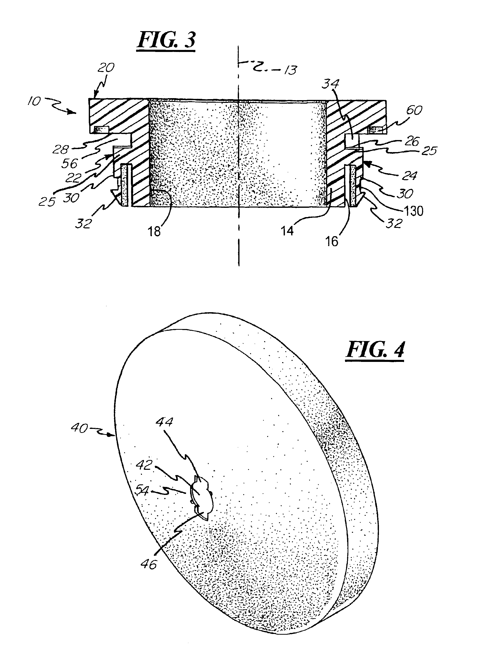
Figure 3
Abstract
Description
REFERENCE TO PROVISIONAL APPLICATION
[0001] This application claims benefit of the filing date of U.S. Provisional Application No. 60 / 374,731 filed Apr. 23, 2002.BACKGROUND OF THE INVENTION
[0002] The present invention relates to a fitting for use with air tanks and, more particularly, to a fitting including a twist end bushing for interfacing with an opening in an air tank.
[0003] Air tanks are typically provided with fittings for connection to tubing or other passageways leading to the air tank. In the past, such fittings have been attached to the air tank by means of a bushing welded to an aperture formed through the wall of the tank. Accordingly, production of the tank requires attention to proper formation of the weld connection and a corresponding labor and manufacturing time cost associated with this operation.
[0004] Accordingly, there is a need for a fitting structure for use with air tanks wherein the fitting structure is easily assembled to the tank. In addition, there is a need ...
Examples
Embodiment Construction
[0021]Referring to FIGS. 1-3, the fitting structure of the present invention includes a bushing 10 for mounting to the wall of a tank and for supporting a fitting, illustrated diagrammatically as 12. The bushing includes a cylindrical body 14 defined by a cylindrical outer surface 16 and a cylindrical inner surface 18 wherein the cylindrical inner surface 18 defines a cylindrical aperture through the bushing 10.
[0022]A head portion 20 is formed integrally with and extends radially outwardly from the cylindrical body 14. The head portion 20 defines a tool-engaging portion of the bushing 10 and in the illustrated embodiment is provided with a hexagonal shape for engagement with a wrench.
[0023]A pair of locking members 22, 24 are located on diametrically opposite sides of the cylindrical body 14. Each locking member 22, 24 includes a base portion 25 extending radially from the outer surface 16 of the cylindrical body 14 and includes an upper surface 26 facing toward a lower surface 28 ...