
Programmable thermostat incorporating a display screen selectively presenting system modes that includes a simple mode
a programmable thermostat and display screen technology, applied in the field of programmable thermostats, can solve the problems of difficult programing, difficult for the average user to readily understand, and the user interfaces employed in prior art programmable interfaces are not highly intuitive, and achieve the effect of simple mode of information and/or operation, easy programing for users
Patent Information
- Authority / Receiving Office
- US · United States
- Patent Type
- Patents(United States)
- Current Assignee / Owner
- Publication Date
- 2006-04-18
Smart Images
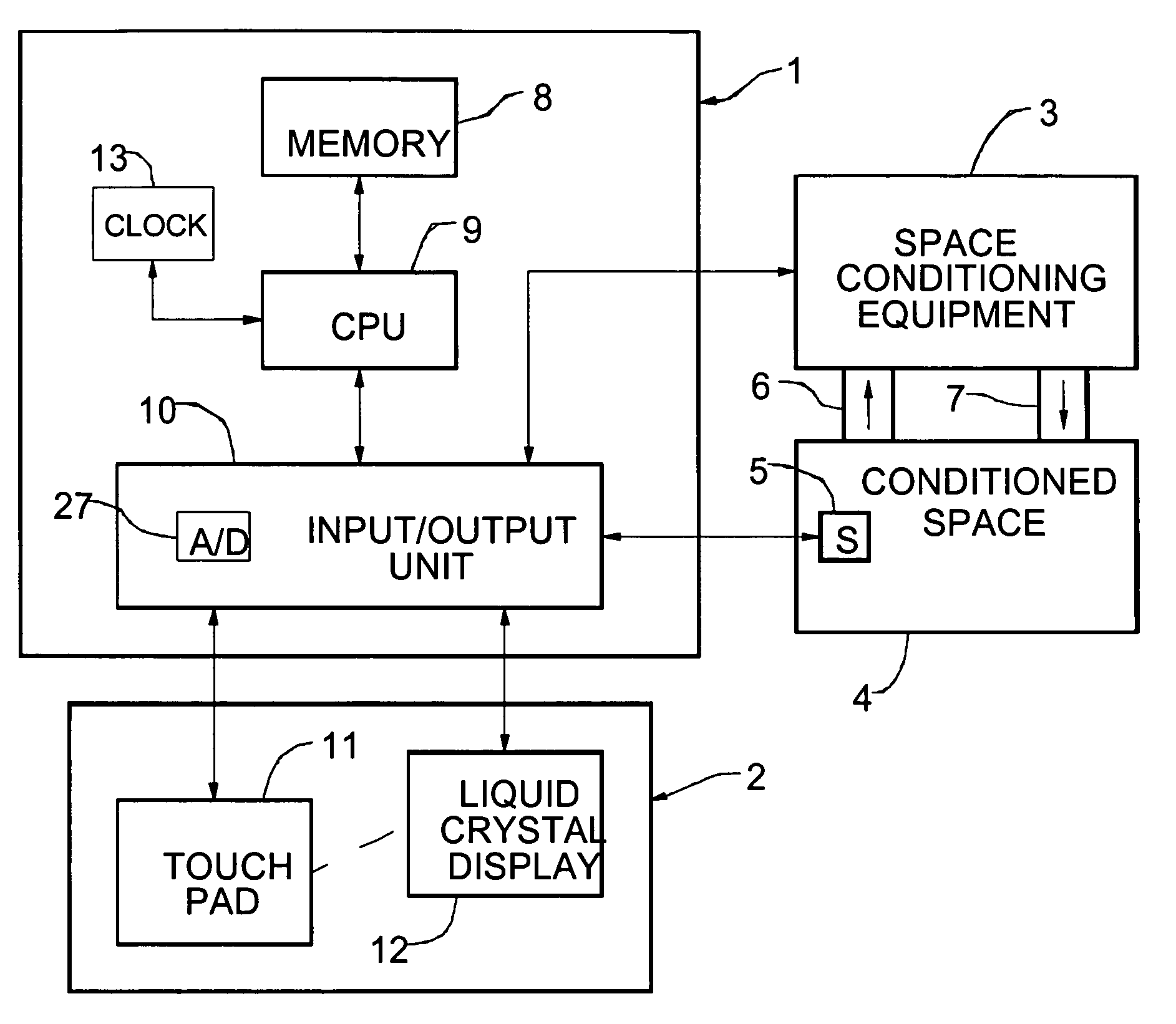
Figure 1 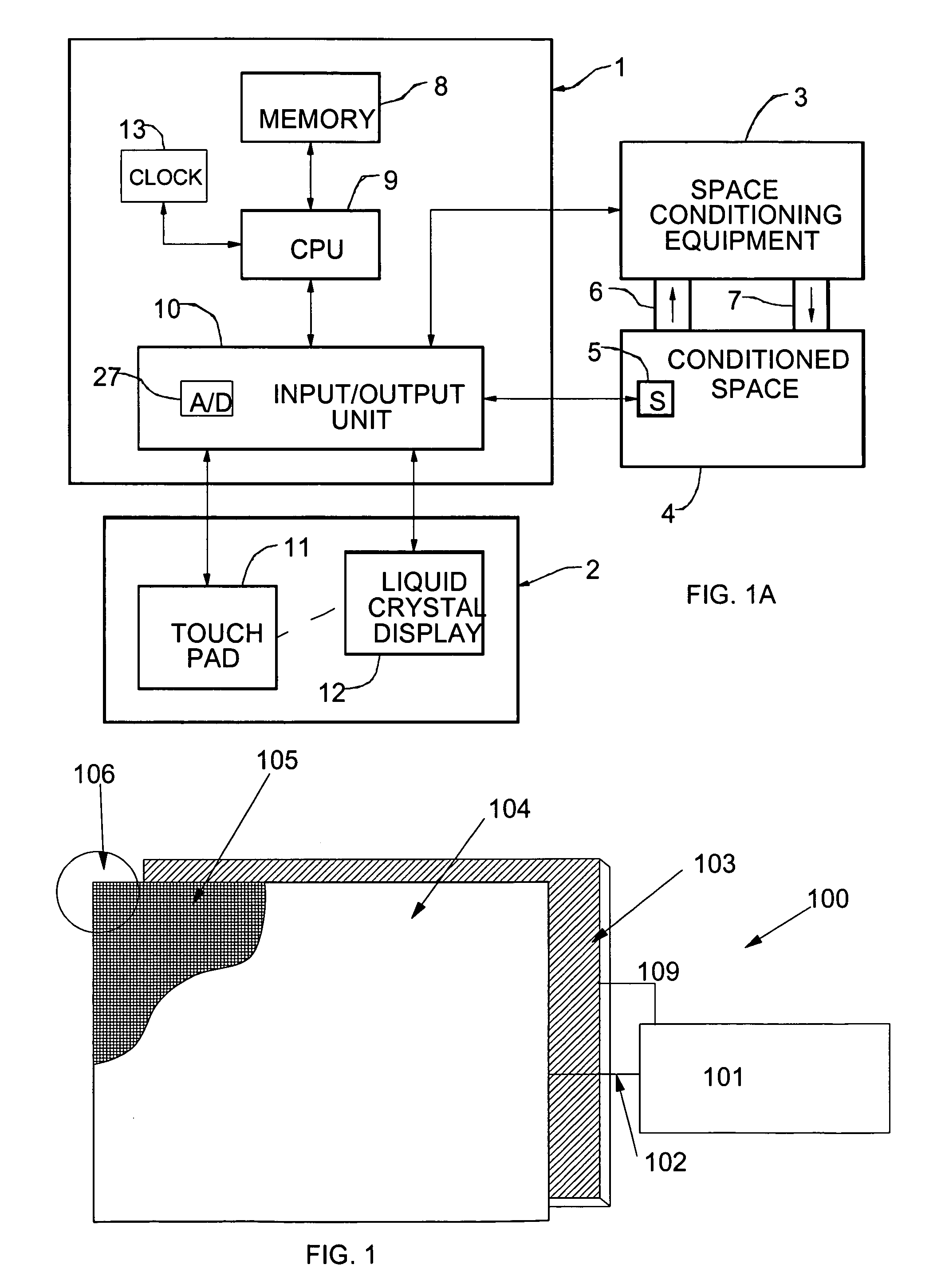
Figure 2 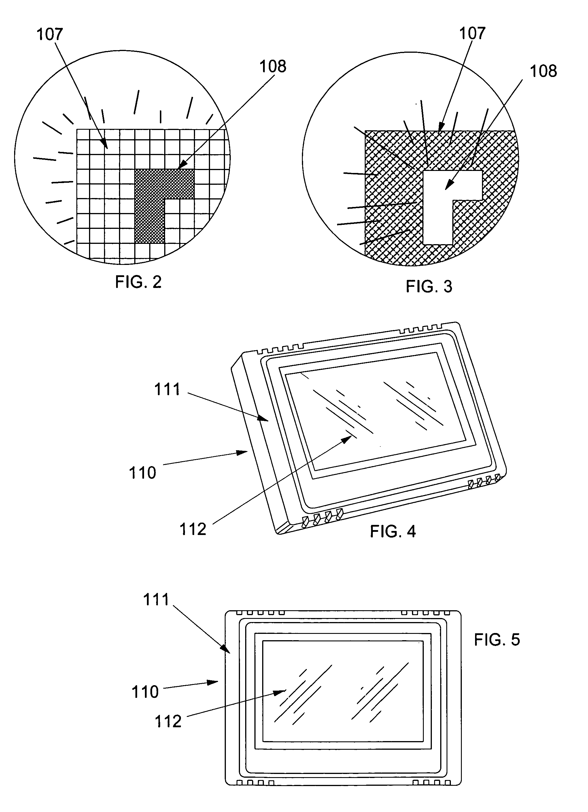
Figure 3
Abstract
Description
CROSS-REFERENCE TO RELATED APPLICATIONS
[0001] This application is a continuation in part of pending U.S. patent application Ser. No. 10 / 654,235 filed Sep. 3, 2003. “PROGRAMMABLE THERMOSTAT INCORPORATING A LIQUID CRYSTAL DISPLAY SELECTIVELY PRESENTING ADAPTABLE SYSTEM MENUS INCLUDING CHANGEABLE INTERACTIVE VIRTUAL BUTTONS”.FIELD OF THE INVENTION
[0002] The present invention relates to a programmable thermostat incorporating an interactive liquid crystal display (LCD) or other display screen, and, more particularly, to such a thermostat in which the display screen selectively presents a more complex mode of information or operation and an alternate simpler mode of information or operation, in order to simplify a user interface with the programmable thermostat.BACKGROUND OF THE INVENTION
[0003] Thermostats have been used for many years as temperature sensitive switches which control heating and / or cooling equipment for conditioning a space in which the thermostat, or a temperature sensor co...
Examples
Embodiment Construction
)
[0045]Referring first to FIG. 1A, a user programmable thermostat system includes a processor 1, a touch screen 2 and a temperature sensor 5 which is disposed in a conditioned space 4. It will be understood that the processor 1 and the touch screen 2 are typically situated in a common housing (shown in an exemplary form in FIG. 5). The sensor 5 may also be situated in the common housing or remotely as shown, all as very well known in the art. The common housing is usually, but not necessarily, placed in the conditioned space 4. Thus, those skilled in the art will understand that the block diagram of FIG. 1A is very general in order to best explain the invention.
[0046]The processor 1 includes a central processing unit (CPU) 9 in communication with a memory 8 for storing data and program information and also, via an input / output unit (I / O unit) 10, a touch pad 11 and an LCD 12 which together constitute the touch screen 2. The memory 8 may include a read-only part which is factory-prog...