
Ratchet coupling means for a driving tool
a technology of ratchets and coupling means, which is applied in the direction of wrenches, screwdrivers, clutches, etc., can solve the problems of easy jumping off and the torque of this type of ratchet socket wrenches
Patent Information
- Authority / Receiving Office
- US · United States
- Patent Type
- Patents(United States)
- Current Assignee / Owner
- Publication Date
- 2006-06-06
- Estimated Expiration
- Not applicable · inactive patent
Smart Images
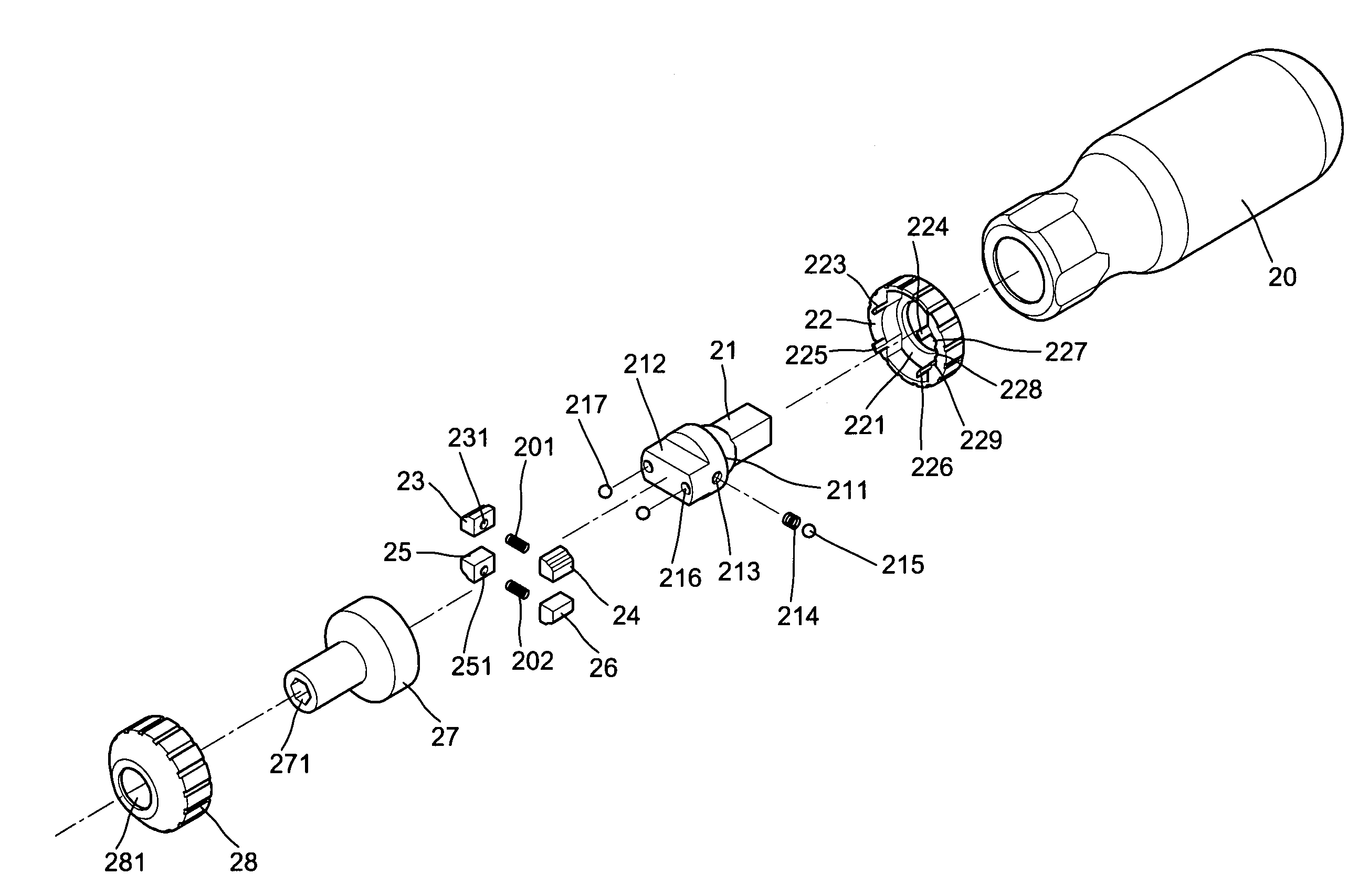
Figure 1 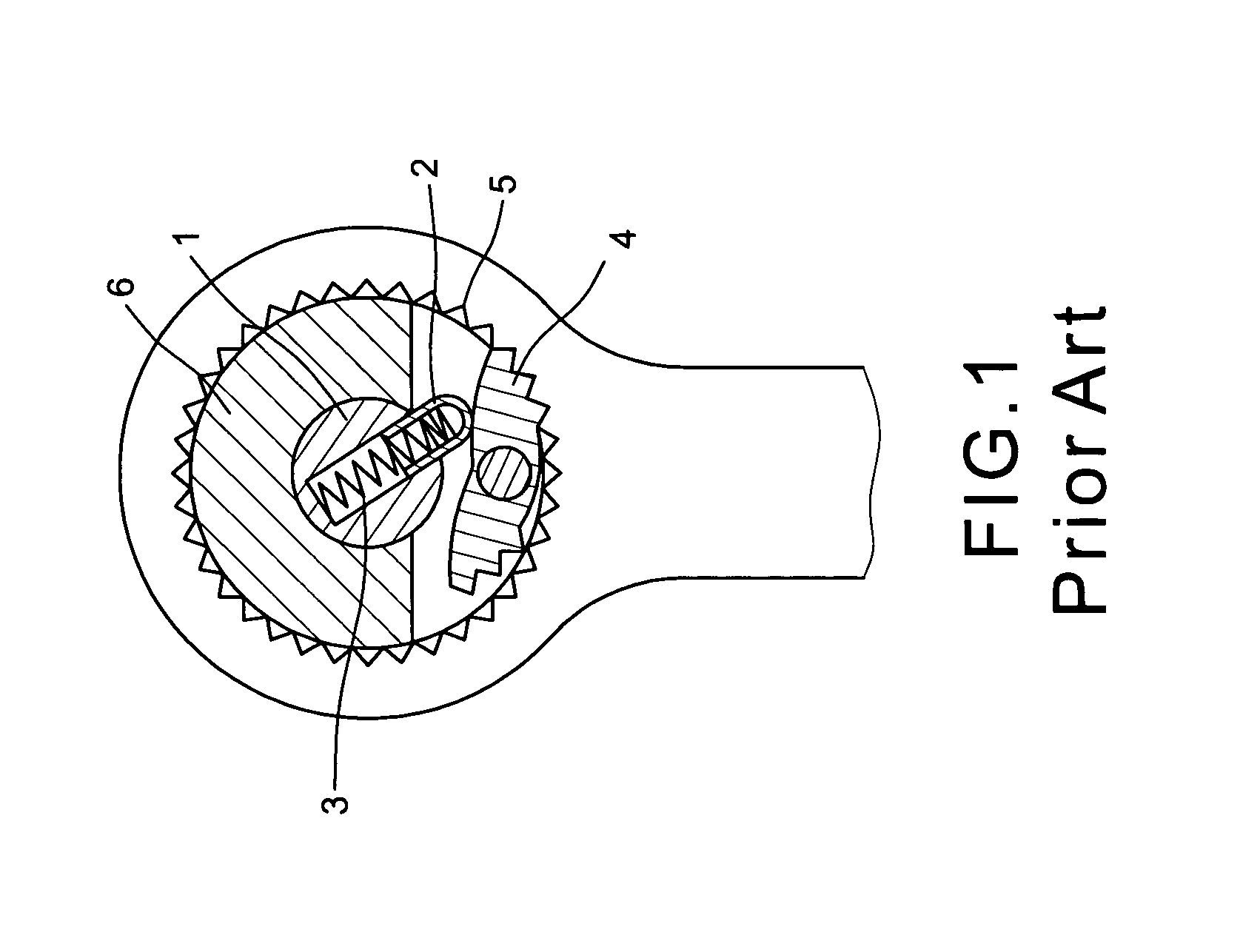
Figure 2 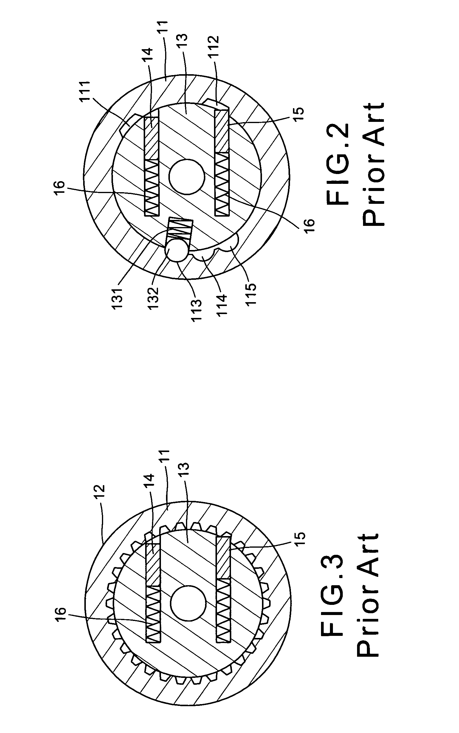
Figure 3
Abstract
Description
BACKGROUND OF THE INVENTION
[0001] The present invention relates to the ratcheted driving tools and more particularly to an improvement in ratchet coupling means for a driving tool.
[0002] As we know that a ratchet checking structured driving tool provides great convenience. This driving tool can fasten or unfasten a bolt or its equivalents by rotating it clockwise, counterclockwise and / or idle running backward. FIG. 1 shows a ratcheted wrench which uses a swivel bottom 1 to control a stir rod 2. The stir rod 2 is biased by a spring 3 and pushes a ratchet plate 4 becoming oblique on single direction and checking the teeth of the ratchet 5 to enable the driving rod 6 to be rotated on single direction so as to drive a working piece. But the torque of this type of ratchet socket wrench is not so strong and easy to jump off.
[0003] FIGS. 2 and 3 show an structurally improved prior art ratchet driving tool which has a control ring 11, a ratchet ring 12, a driving rod 13 and a pair of checking ...
Examples
Embodiment Construction
[0026]With reference to the drawings and initiated from FIGS. 4 to 8, the improvement in ratchet coupling means for a driving tool of the present invention comprises a handle 20 having a stepped central bore, a driving member 21 having a rectangular rear end fixed into the central bore of the handle 20, a retaining ring 211 on a middle portion engaged within a circular depression in a control ring 22 which surrounds the driving member 21 without sliding out, a flat rectangular front end to form a pair of receiving spaces 212 and 218 on the top and the underside thereof each receives a pair of checking blocks 23, 24, 25 and 26.
[0027]The checking blocks 23, 24, 25 and 26 each has a circular recess 231, 241, 251 and 261 in inner side facing each other, wherein the blocks 23 and 24 are biased by a spring 201 and the blocks 25 and 26 are biased by a spring 202 therebetween, a circular recess 213 in a left side of the driving member 21 engaged with a spring 214 and a steel ball 215 and a ...