
Corrugated tube fitting
a technology of corrugated tubes and fittings, which is applied in the direction of fluid pressure sealing joints, hose connections, mechanical equipment, etc., can solve the problems of limited ability to tighten parts, lack of precision in cutting the end of the tubing, and range of known fittings, etc., to achieve good mechanical strength and sealing performance, the effect of minimal complexity and expens
Patent Information
- Authority / Receiving Office
- US · United States
- Patent Type
- Patents(United States)
- Current Assignee / Owner
- Publication Date
- 2006-06-06
Smart Images
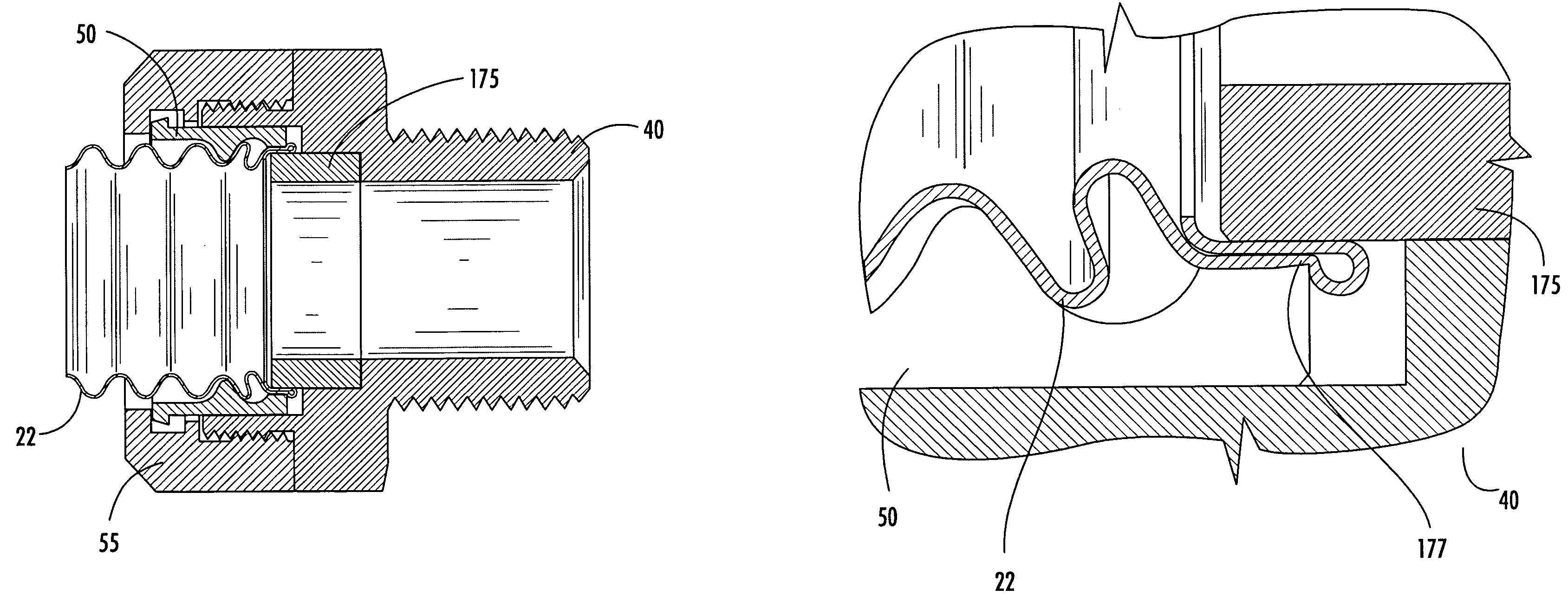
Figure 1 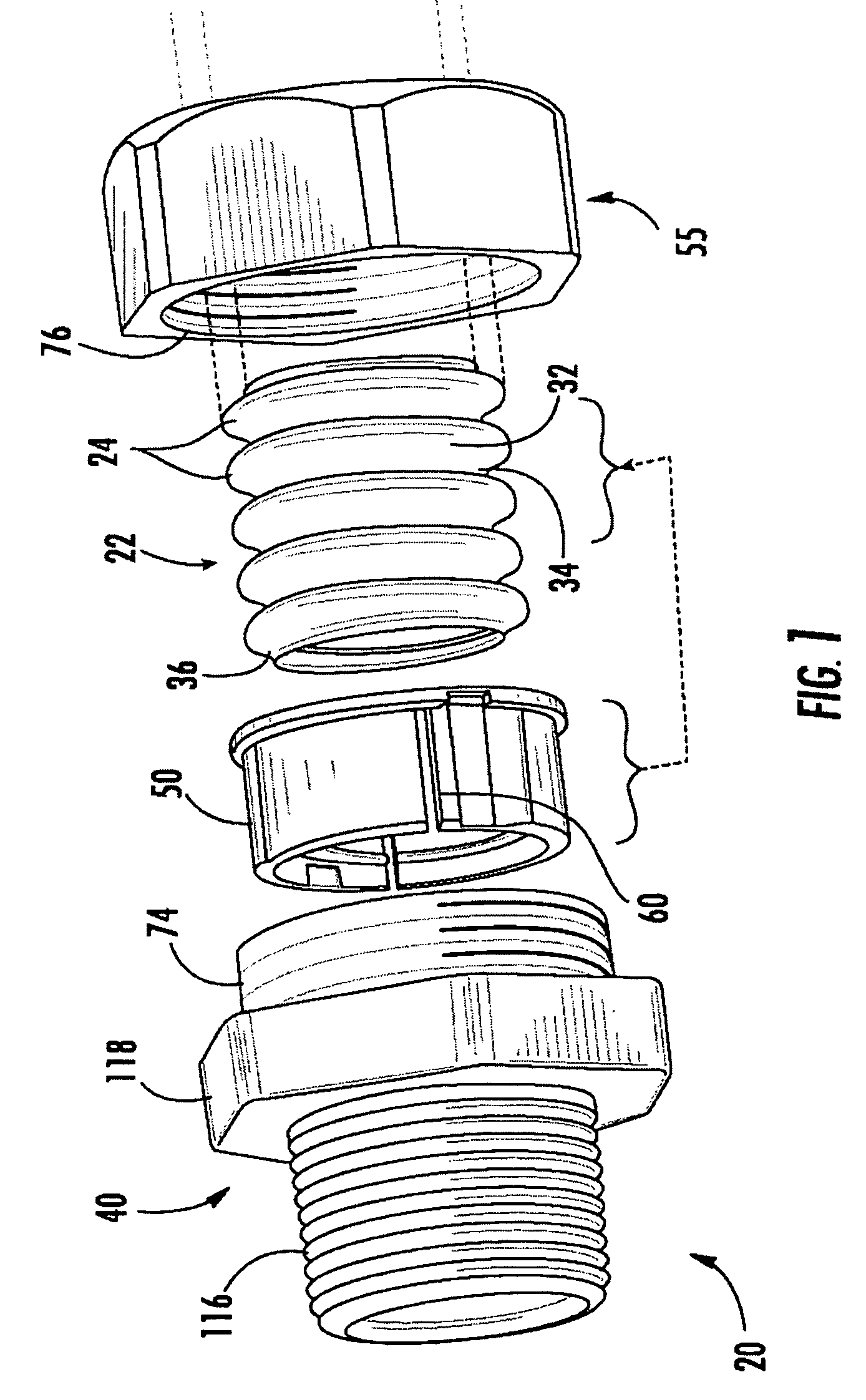
Figure 2 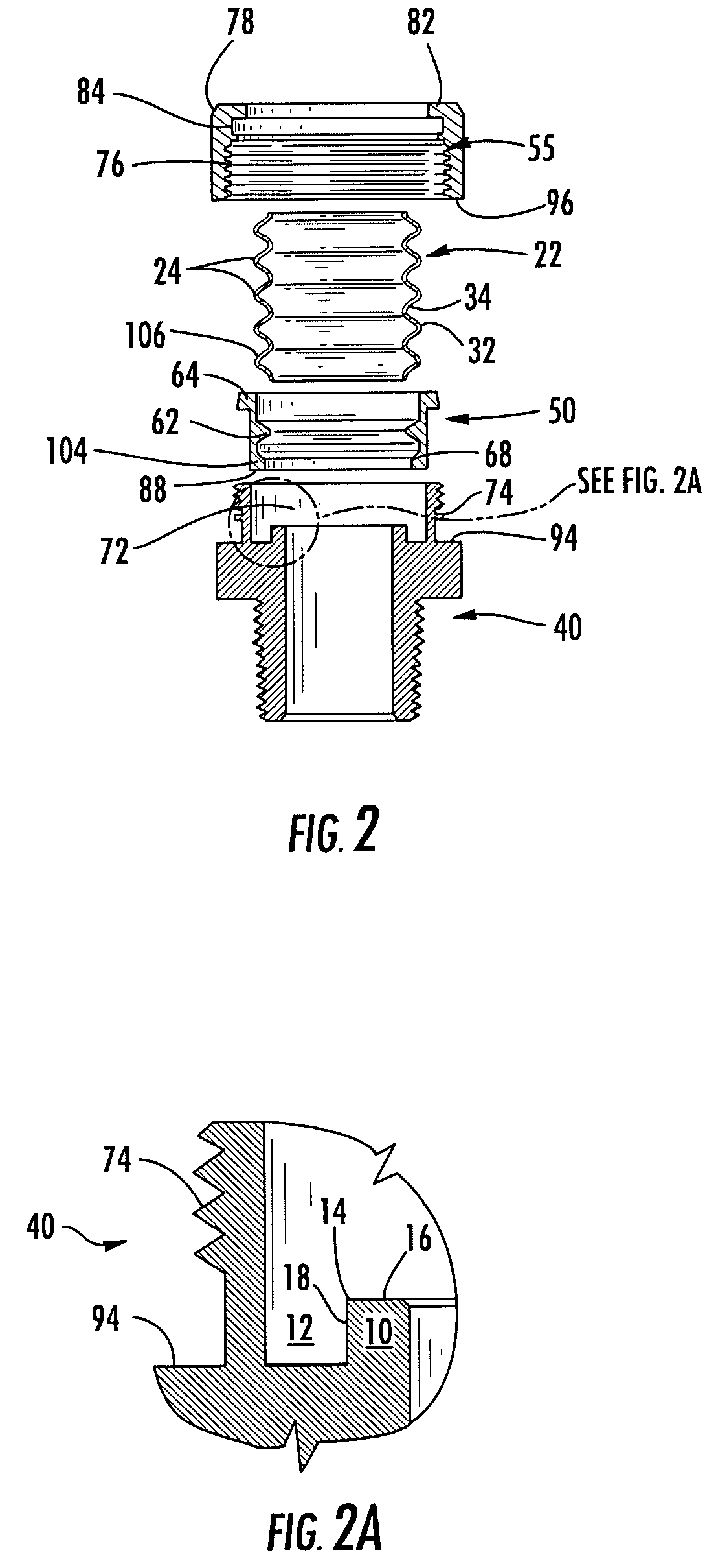
Figure 3
Abstract
Description
BACKGROUND OF THE INVENTION
[0001] 1. Field of the Invention
[0002] The invention concerns a fitting for sealed termination of a length of corrugated tubing, especially corrugated stainless steel gas lines, of the type that includes a generally cylindrical fitting body and nut, threaded together on opposite sides of a tubing retainer. The retainer has one or more inward rings or ridges, complementary with the tubing corrugations. The retainer grips the corrugated tubing near a cut end. Tightening the nut on the fitting body forces the retainer to advance the cut end of the tube axially into the fitting body.
[0003] According to an inventive aspect, the cut end is carried by the retainer against an axially facing surface in the fitting body surrounded by an annular groove. The annular groove is sized to receive the end of the retainer, with a slight annular clearance approximating the thickness of the tubing material. The endmost corrugation ridge is folded over into the annular groove, fl...
Examples
Embodiment Construction
[0039]An inventive fitting 20 for an end of a length of tubing 22 such as corrugated stainless steel tubing is shown in FIGS. 1–7, which include exemplary variations as discussed herein. FIG. 1 shows the respective parts in an exploded view as a cut end of a length of tubing of indefinite length, to be terminated by fitting 20. The termination can be for any of the various purposes that might benefit from a sealed connection to the tubing, especially mechanical attachment and hermetic sealing.
[0040]In the non-limiting example shown in FIG. 1, the fitting forms a union between the tubing and a pipe thread on a generally cylindrical fitting body 40. This sort of union is typically used for making a connection between the flexible corrugated tubing and a fixed pipe, manifold, apparatus housing or other station disposed along a flow path for gas or fluid in communication with tubing 22. The fitting body 40 has a tapered thread facing away from tubing 22 and wrench flats. The invention i...