
Head gimbal assembly and method for manufacturing the same
a technology of head gimbal and assembly, which is applied in the direction of maintaining the head carrier alignment, recording information storage, instruments, etc., can solve the problems of insufficient measures to prevent electrostatic discharge, damage to discharge unfortunately damages the magnetic head element at a constant rate, so as to prevent the damage of electrostatic discharge, reduce the contact resistance, and reduce the contact resistance
Patent Information
- Authority / Receiving Office
- US · United States
- Patent Type
- Patents(United States)
- Current Assignee / Owner
- Publication Date
- 2006-08-22
- Estimated Expiration
- Not applicable · inactive patent
Smart Images
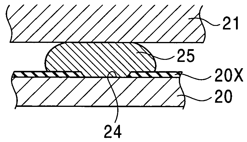
Figure 1 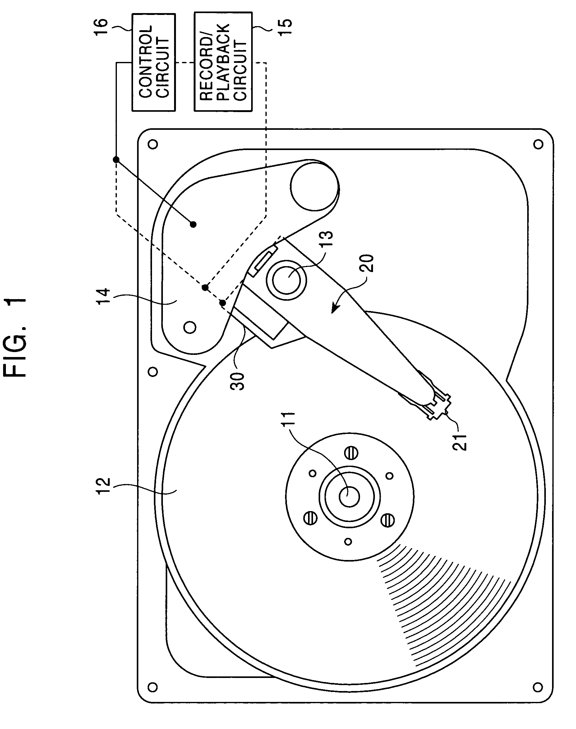
Figure 2 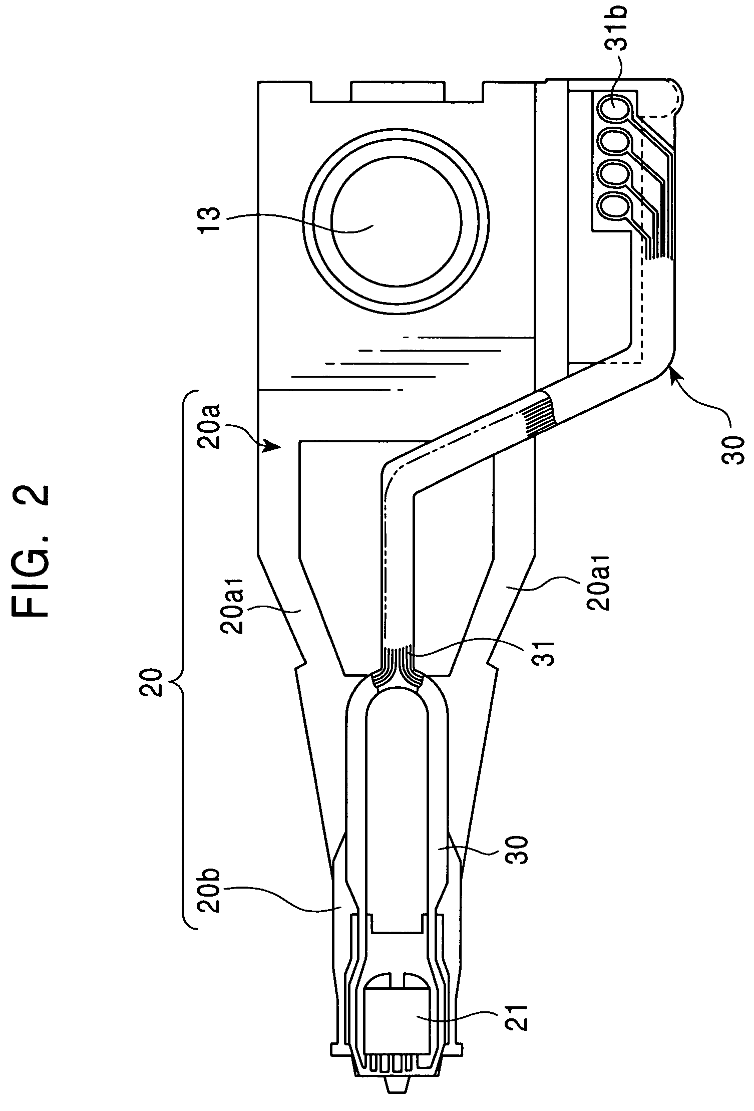
Figure 3
Abstract
Description
[0001] This application claims the benefit of priority to Japanese Patent Application 2002-304632, filed on Oct. 18, 2002.BACKGROUND OF THE INVENTION
[0002] 1. Field of the Invention
[0003] The present invention relates to head gimbal assemblies (HGAs) and methods for manufacturing the head gimbal assemblies.
[0004] 2. Description of the Related Art
[0005] Head gimbal assemblies are widely used for hard disc drives (HDDs). Such a head gimbal assembly includes a load beam, a metal flexure fixed on the leading end of the load beam, and a slider bonded on an end of the flexure. This slider has a thin film magnetic head element such as a magnetoresistive element (MR element) or a giant magnetoresistive element (GMR element). In this head gimbal assembly, a charged slider may cause electrostatic discharge (ESD), which damages the magnetic head element on the slider. To solve this problem, conductive adhesive resin is conventionally disposed between the flexure and the slider to dissipate the char...
Examples
Embodiment Construction
[0021]FIG. 1 shows the entire structure of a hard disc drive having a head gimbal assembly according to the present embodiment. A hard disc 12, which is a magnetic disc, rotates around a rotating shaft 11. Another rotating shaft 13, which is disposed adjacent to the hard disc 12, supports the base of a gimbal suspension 20. This gimbal suspension 20 is rotatable around the rotating shaft 13. A free end of the gimbal suspension 20 is bonded to a slider 21 having a thin film magnetic head element such as a magnetoresistive element or a giant magnetoresistive element. When an actuator 14 rotates the gimbal suspension 20 around the rotating shaft 13, the slider 21 reciprocates substantially in the radial direction of the hard disc 12.
[0022]Referring to FIG. 2, the gimbal suspension 20 includes a load beam 20a, which is the base of the gimbal suspension 20 supported by the rotating shaft 13, and a stainless-steel flexure (flexure base) 20b, which is laser-welded to the leading end of the...