
Connectors, tracks and system for smooth-faced metal framing
a technology of connecting tracks and metal framing, applied in the direction of girders, walls, joists, etc., can solve the problems of time and money of clients, and achieve the effects of convenient modification, convenient screwing and securement, and safer and easier us
Patent Information
- Authority / Receiving Office
- US · United States
- Patent Type
- Patents(United States)
- Current Assignee / Owner
- Publication Date
- 2006-10-31
- Estimated Expiration
- Not applicable · inactive patent
Smart Images
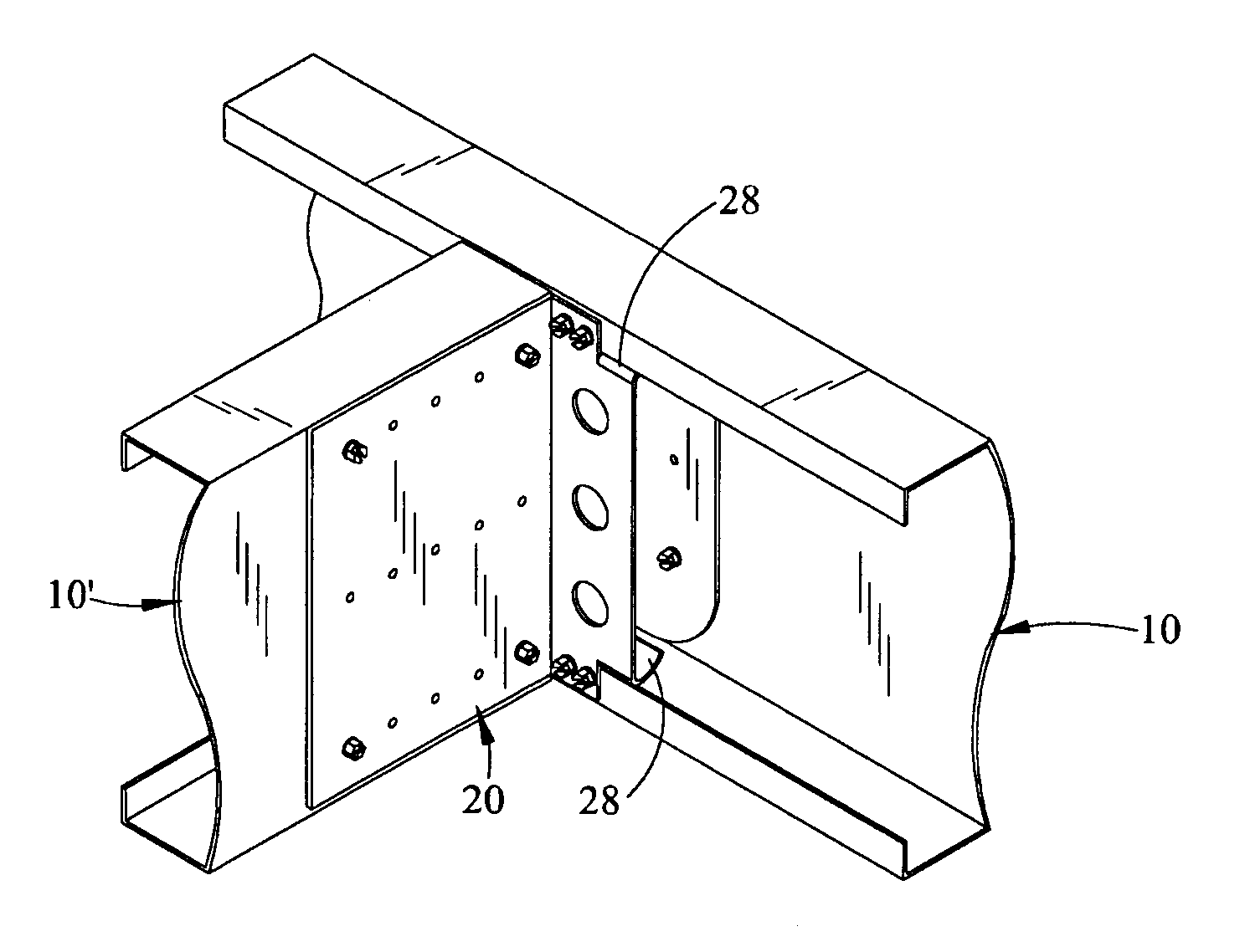
Figure 1 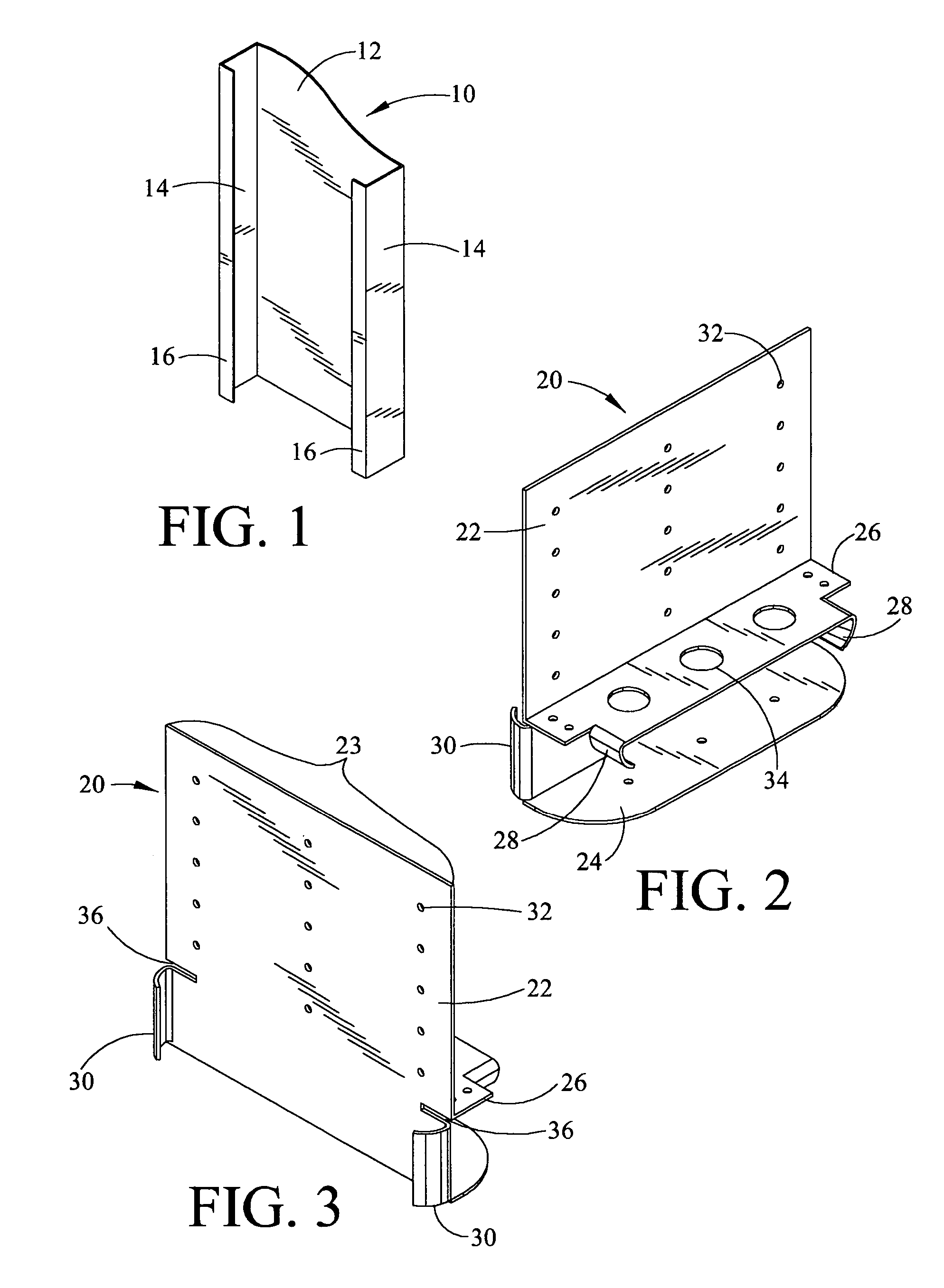
Figure 2 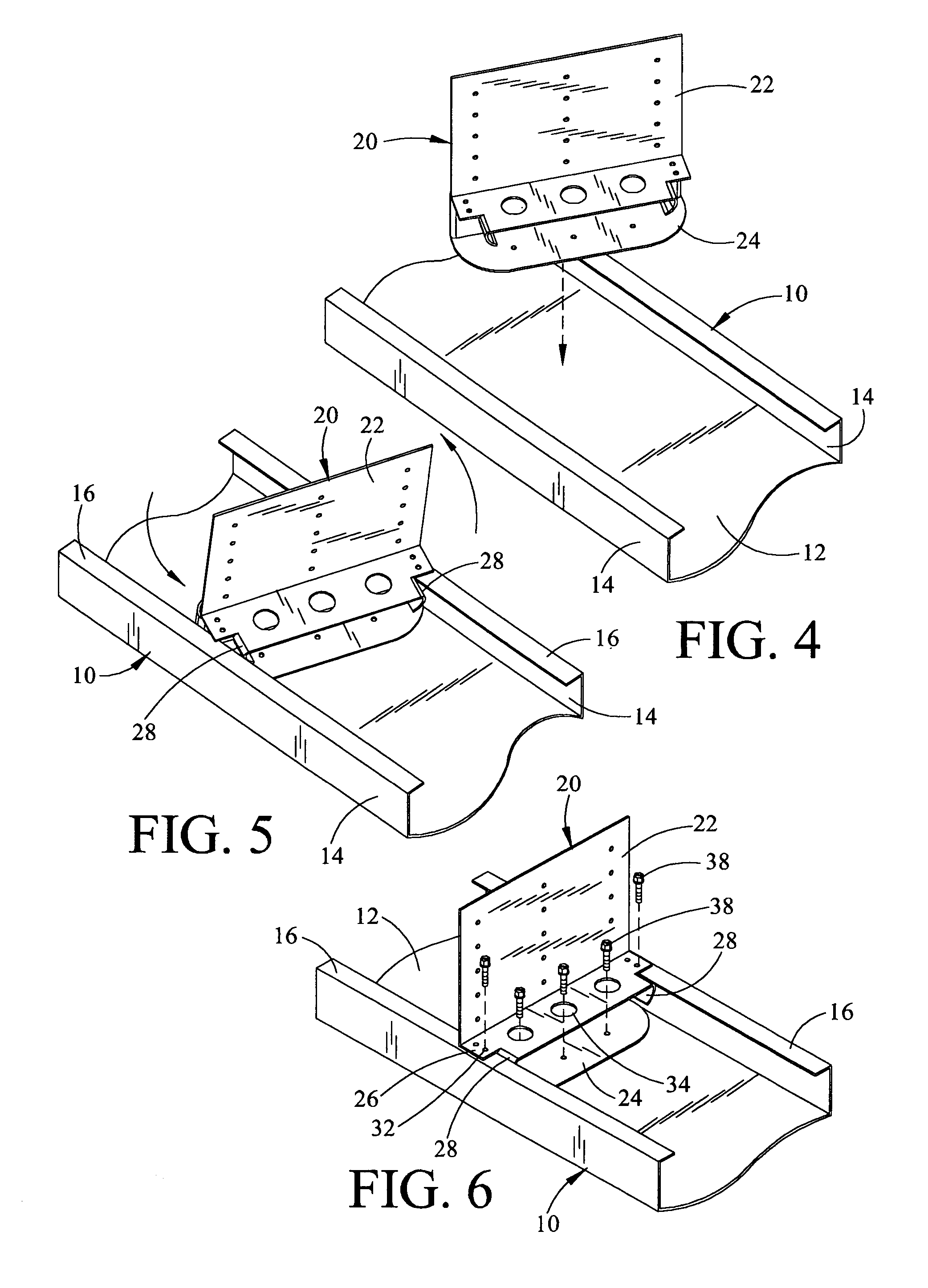
Figure 3
Abstract
Description
CROSS-REFERENCE TO RELATED PATENT APPLICATIONS
[0001] This is a (first) division of U.S. Non-provisional application Ser. No. 10 / 046,127, filed Jan. 9, 2002 now U.S. Pat. No. 6,609,344, and granted on Aug. 26, 2003, which application is based in substantial part upon and claims the benefit of U.S. Provisional Application No. 60 / 334,283 filed Nov. 21, 2001.STATEMENT REGARDING FEDERALLY SPONSORED RESEARCH OR DEVELOPMENT
[0002] The subject invention is not the result of or in any way related to federally sponsored research or development.BACKGROUND OF INVENTION
[0003] 1. Field of Invention
[0004] The present invention relates to materials and methods for metal framing. In particular, this invention describes an improved system of metal framing that employs specially configured connectors and tracks that leave the faces of the resulting framed structure smooth and easy to cover.
[0005] This first divisional application claims a species of structurally related connectors having a connector body, b...
Examples
Embodiment Construction
Prior Art Framing Members
[0145]A conventional U-channel metal framing member or stud 10 is shown in FIG. 1. Framing member 10 comprises a base 12, two sidewalls 14 which extend perpendicular from base 12, and two lips 16 which extend inward from the tops of sidewalls 14 perpendicular thereto and parallel to base 12.
[0146]Member 10 can be of any length, width and depth. Typically member 10 will have a width defined by the width of base 12 that is at least twice its depth defined by the width of sidewalls 14. When substituting for 2″×4″ framing lumber, member 10 will have sidewalls 14 of approximately 2 inches in width and base 12 of approximately 4 inches in width. Lips 16 in this case will extend approximately ⅛ to ½ inch inward from sidewalls 14, although other depths are also possible.
[0147]Member 10 is rolled from steel or aluminum, but could be made of any metal, including stainless steel. The weight and strength of member 10 will be determined by its gauge, which will vary depe...