
Charging and discharging control circuit, and charging type power supply device
a control circuit and power supply device technology, applied in secondary battery servicing/maintenance, emergency protection arrangements for limiting excess voltage/current, safety/protection circuits, etc., can solve the problem of high probability that the secondary battery will attain an overcharge state or an overdischarge state, risk of ignition or explosion of the battery, and electrolyte decomposition, etc. problem, to achieve the effect of increasing the efficiency of testing tim
Patent Information
- Authority / Receiving Office
- US · United States
- Patent Type
- Patents(United States)
- Current Assignee / Owner
- Publication Date
- 2009-02-03
Smart Images
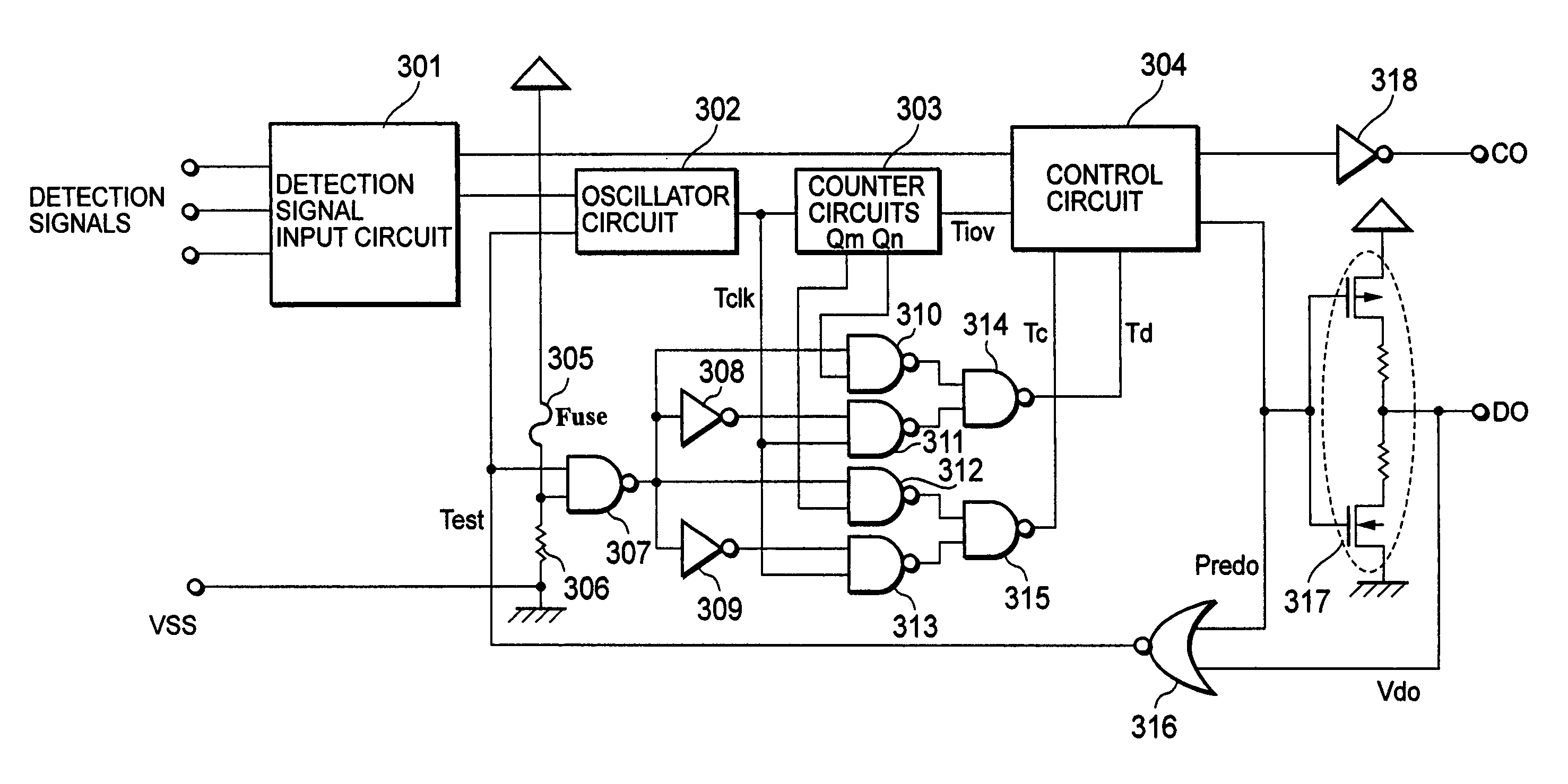
Figure 1 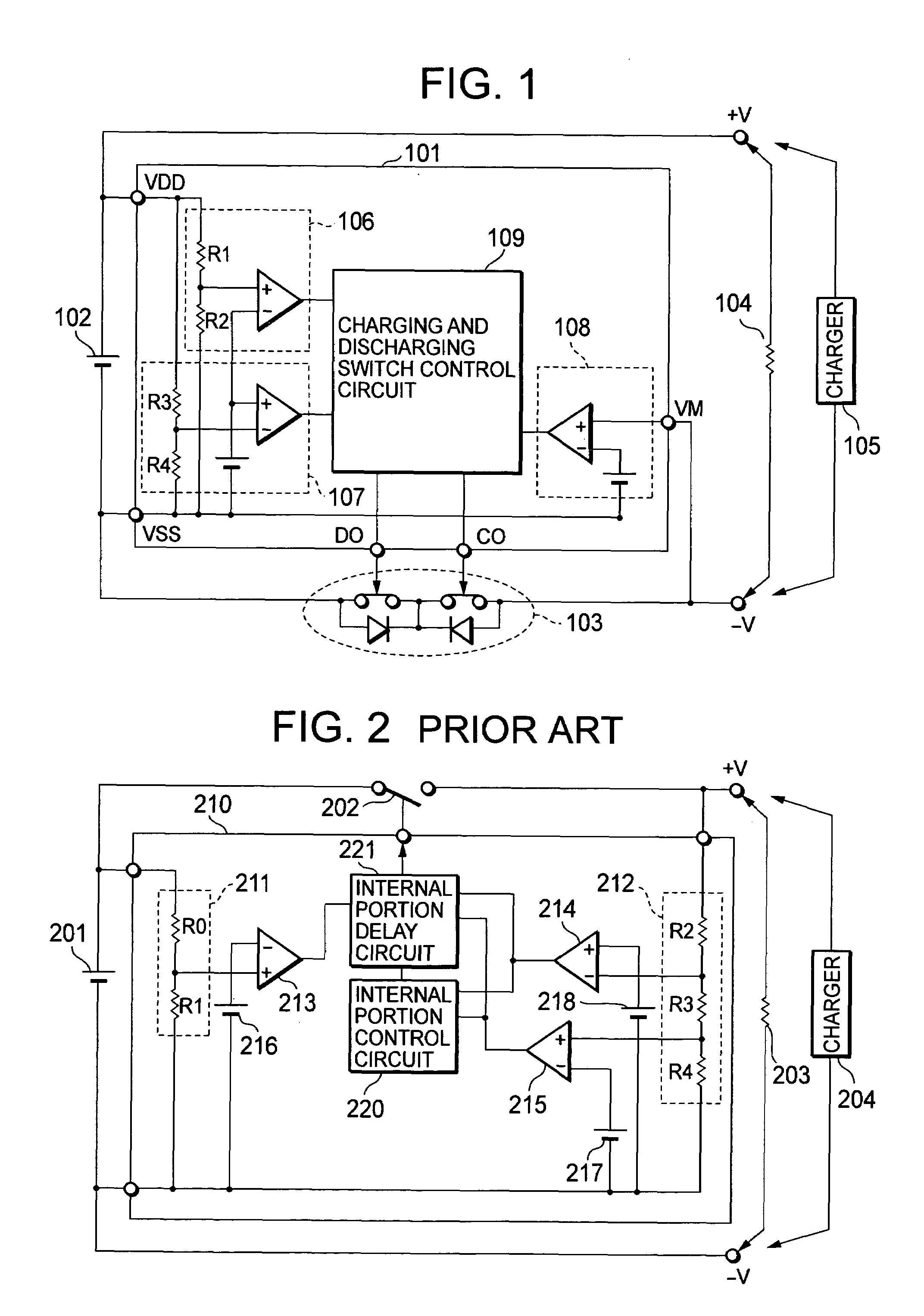
Figure 2 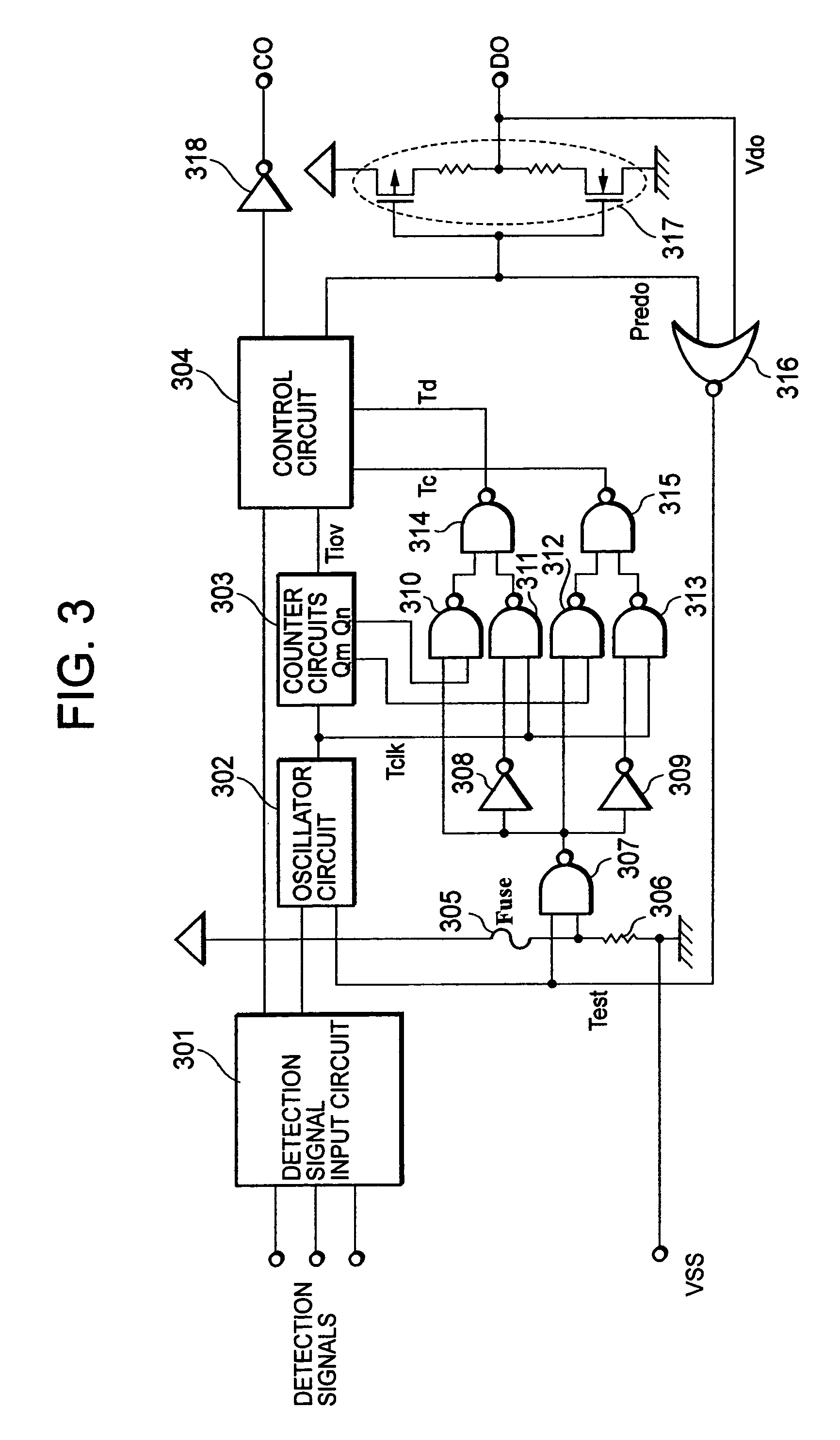
Figure 3
Abstract
Description
BACKGROUND OF THE INVENTION
[0001] 1. Field of the Invention
[0002] The present invention relates to a charging and discharging control circuit and a charging type power supply device of a secondary battery equipped with the charging and discharging control circuit. In particular, the present invention relates to a method of switching into and out of a testing state for evaluating the characteristics of the charging and discharging control circuit.
[0003] 2. Description of the Related Art
[0004] The features of a lithium ion secondary battery which has greatly contributed to the popularization of mobile devices typified by a mobile telephone and a PHS are its small size, lightweight, and large capacity. Those features have led to realization of long time driving and lightness of the mobile devices. However, since a secondary battery is repeatedly charged and discharged, there is a high probability that the secondary battery will attain an overcharge state or an overdischarge state. If the s...
Examples
Embodiment Construction
[0029]Embodiments of the present invention are explained in detail below with reference to the drawings. FIG. 1 is a block diagram of a charging and discharging control circuit 101 according to one embodiment of the present invention. A charging and discharging switch control circuit 109 includes a delay circuit which determines a delay time for the charging and discharging control circuit. FIG. 3 shows details of the charging and discharging switch control circuit 109 including the delay circuit of FIG. 1. FIG. 4 shows a configuration of a charging type power supply device that utilizes a charging and discharging control circuit 401 proposed by the present invention.
[0030]The charging and discharging control circuit 401 of FIG. 4 includes a positive electrode connection terminal VDD and a negative electrode connection terminal VSS of a secondary battery 402, an over-current detection terminal VM, a charging control output terminal CO, and a discharging control output terminal DO. T...