
Control arm structure for wheel suspensions of motor vehicles, and method of making such a control arm structure
a technology of control arm and suspension, which is applied in the direction of non-disconnectible pipe joints, fastening means, lamination, etc., can solve the problems of high ductility in the relevant processing state, counter to the desired high mechanical strength, and requiring complicated heat treatment, etc., to achieve low ductility potential, reduce weight, and sufficient strength
Patent Information
- Authority / Receiving Office
- US · United States
- Patent Type
- Patents(United States)
- Current Assignee / Owner
- Publication Date
- 2009-07-07
- Estimated Expiration
- Not applicable · inactive patent
Smart Images
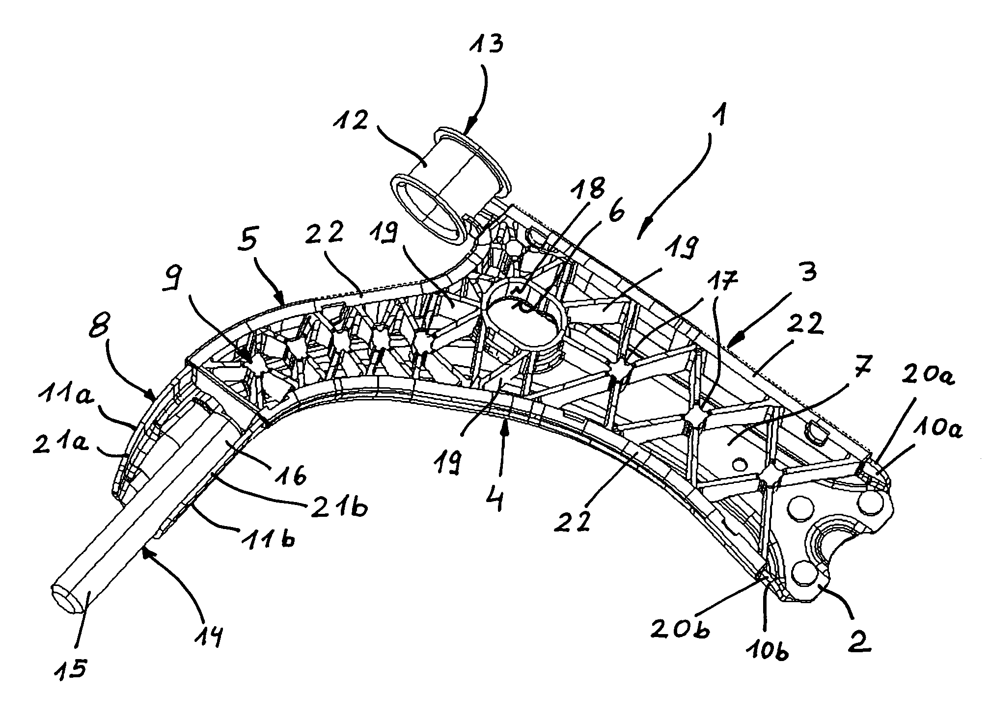
Figure 1 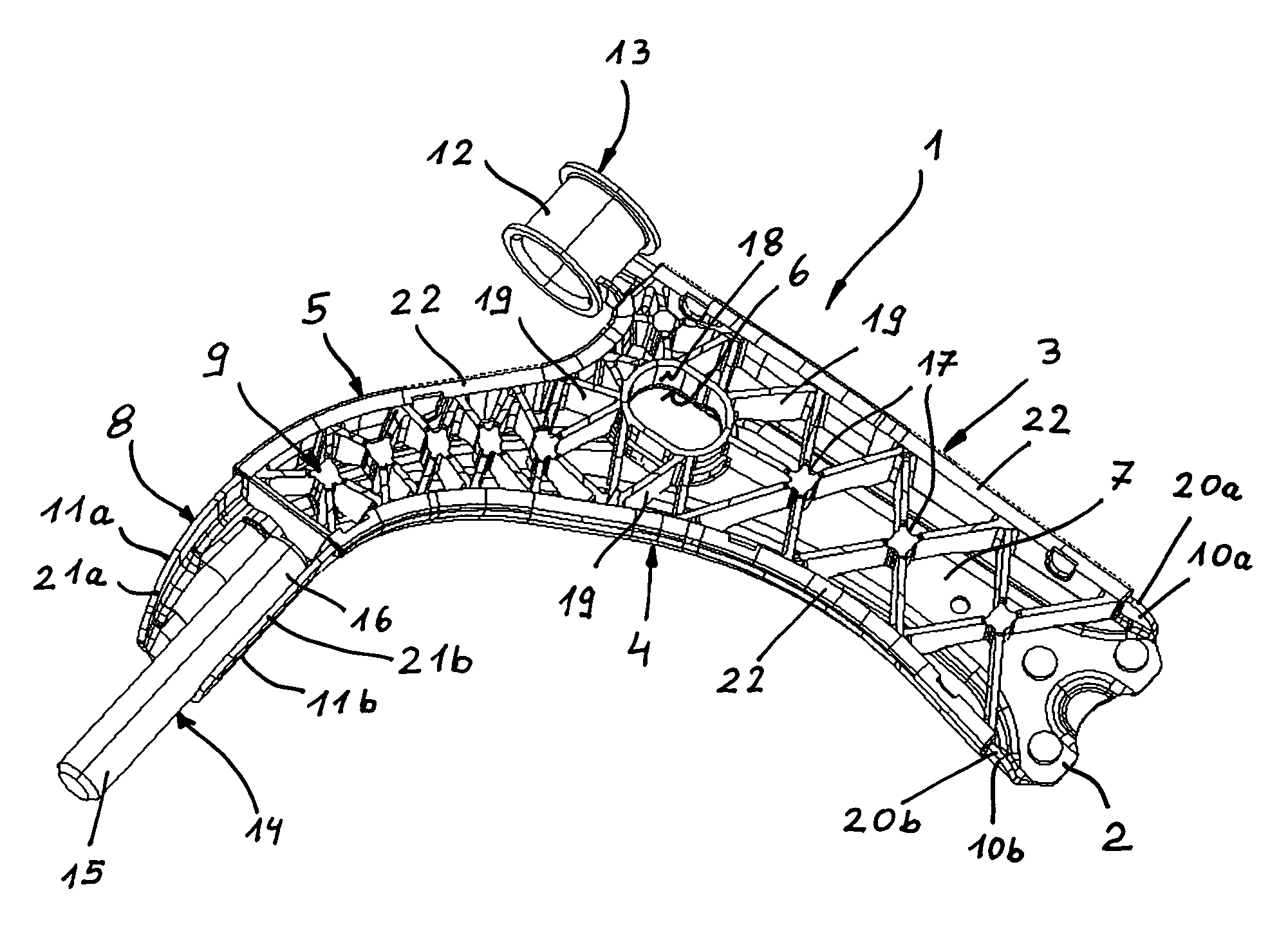
Figure 2
Abstract
Description
CROSS-REFERENCES TO RELATED APPLICATIONS
[0001] This application claims the priority of German Patent Application, Ser. No. 10 2005 004 917.6, filed Feb. 2, 2005, pursuant to 35 U.S.C. 119(a)-(d), the content of which is incorporated herein by reference.BACKGROUND OF THE INVENTION
[0002] The present invention relates, in general, to a control arm structure for wheel suspensions of motor vehicles, and to a method of making such a control arm structure.
[0003] Nothing in the following discussion of the state of the art is to be construed as an admission of prior art.
[0004] U.S. Pat. No. 5,190,803, issued Mar. 2, 1993, discloses a lightweight structure having a shell-shaped base body which has an interior accommodating reinforcing ribs made from injected-on plastic. Anchors are provided at the connecting points between the base body and the reinforcing ribs to enhance the buckling stability of the base body of steel sheet as well torsional stiffness.
[0005] U.S. Patent. Application Publication ...
Examples
Embodiment Construction
[0023]The depicted embodiment is to be understood as illustrative of the invention and not as limiting in any way. It should also be understood that the drawings are not necessarily to scale and that the embodiments are sometimes illustrated by graphic symbols, phantom lines, diagrammatic representations and fragmentary views. In certain instances, details which are not necessary for an understanding of the present invention or which render other details difficult to perceive may have been omitted.
[0024]Turning now to the drawing, and in particular to FIG. 1, there is shown a control arm structure according to the present invention, generally designated by reference numeral 1. The control arm structure 1 approximates an L-shaped configuration and includes three support regions. On the right-hand side of FIG. 1, there is a first support region 2 which is constructed with a socket of a ball-shaped coupling, not shown in detail, for connection to a hub carrier of a road wheel of a moto...