
Lathe
a technology of lathes and backs, applied in the field of lathes, can solve the problems of serious affecting processing accuracy and safety, correspondingly increasing the forward-backward dimension of the machine, and affecting the processing, so as to reduce the amount of chips, reduce the forward-backward dimension of the entire lathe, and reduce the forward-backward dimension
Patent Information
- Authority / Receiving Office
- US · United States
- Patent Type
- Patents(United States)
- Current Assignee / Owner
- Publication Date
- 2010-05-18
Smart Images
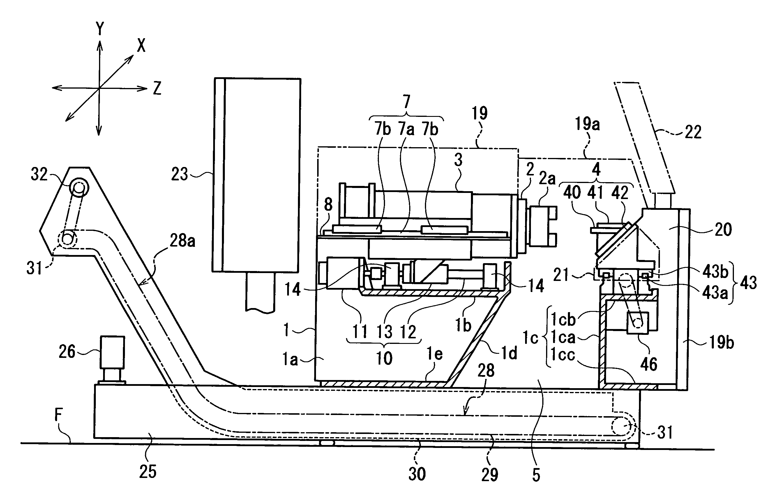
Figure 1 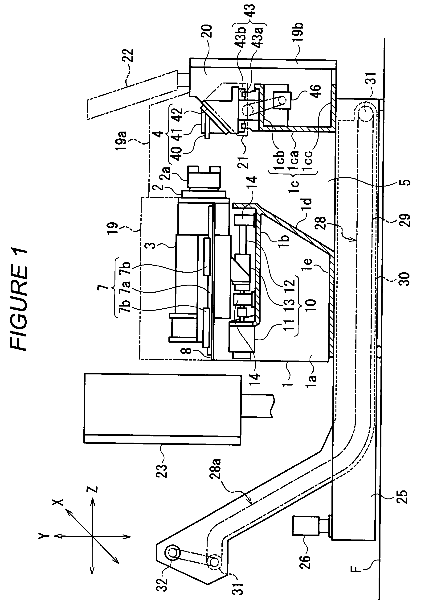
Figure 2 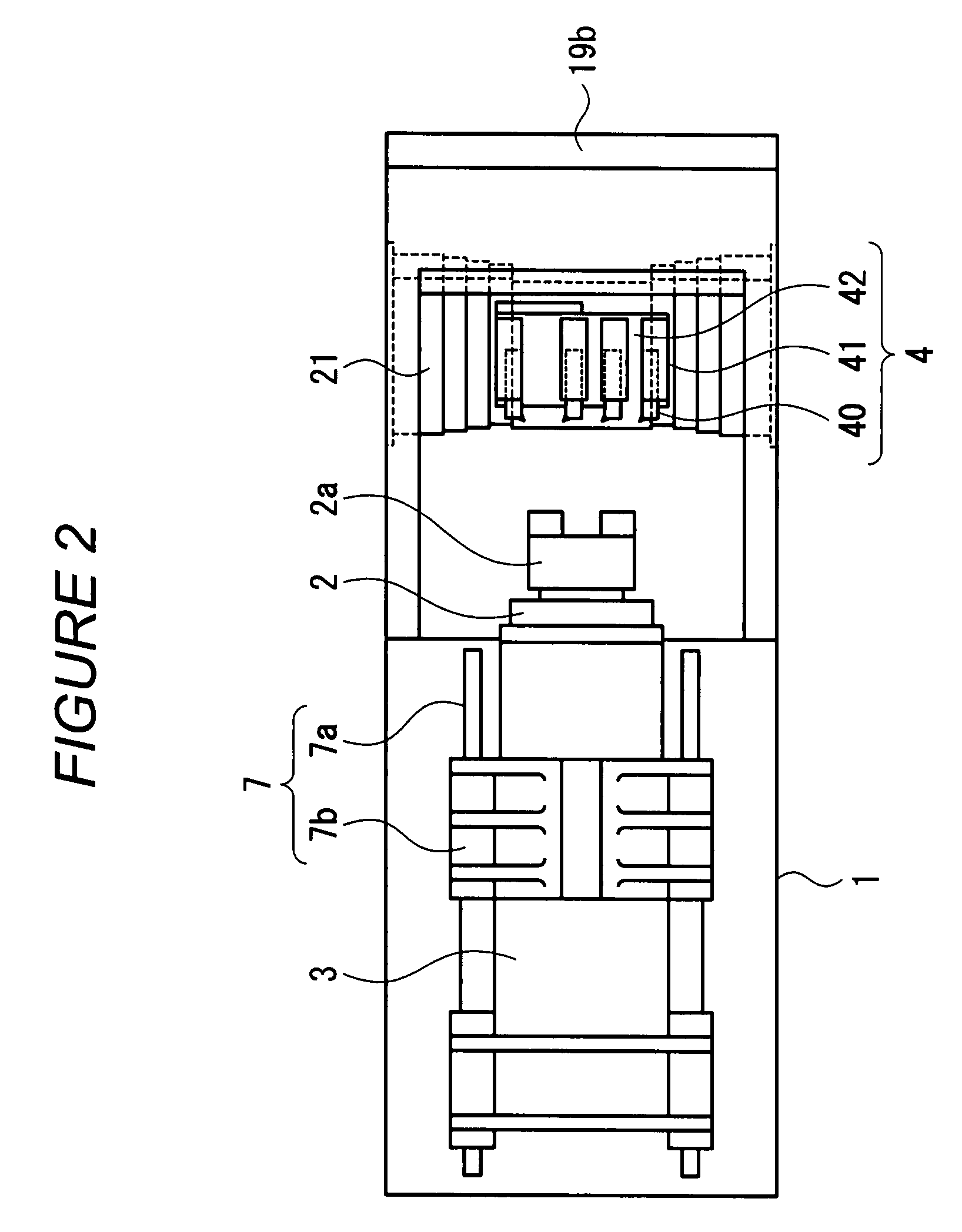
Figure 3
Abstract
Description
FIELD OF THE INVENTION
[0001] The present invention relates to the configuration of a tool feeding shaft of a lathe having a spindle provided in a horizontal directionBACKGROUND OF THE INVENTION
[0002] Conventional lathes having a spindle facing in a horizontal direction are generally of what is called a horizontal bed type in which a tool feeding shaft (X axis and Z axis) is located in a horizontal plane. In one lathe of the horizontal bed type (the Unexamined Japanese Utility Model Application Publication (Jikkai-Sho) No. 62-198032), a plurality of tool holders are arranged in the direction of the X axis. In this lathe, a cross slide that is a member constituting a base on which the tool holders are mounted is horizontally installed in a processing area, and the tool holders are fixed on the cross slide.
[0003] Where the cross slide is horizontally installed as in the case of the lathe in accordance with the Unexamined Japanese Utility Model Application Publication (Jikkai-Sho) No. 62-1...
Examples
Embodiment Construction
[0019]An embodiment of the present invention will be described with reference to FIG. 1 to FIG. 4. The lathe has a headstock 3 supporting a spindle 2 and installed on a bed 1 so as to be movable forward and backward (the direction of a Z axis). The spindle 2 faces in the forward-backward direction (the direction of a Z axis). A spindle chuck 2a is provided at a front end of the spindle 2. A processing means 4 is provide in front of the spindle 2.
[0020]The bed 1 is shaped like a box having a pair of opposite side plate portion 1a, a top plate portion 1b provided in the rear of the side plate portions 1a between upper ends of the side plate portions 1a, and a front plate portion 1c provided between front ends of the opposite side plate portions 1a. The front plate portion 1c has a vertical upright portion 1ca, an upper end horizontal portion 1cb horizontally extended forward from an upper end of the vertical upright portion 1ca, and a lower end horizontal portion 1cc horizontally exte...