
Two-speed PTO stub shaft exchange improvements
a stub shaft and two-speed technology, applied in the direction of interengaging clutches, couplings, gearing, etc., can solve the problems of tedious installation and time-consuming, and achieve the effect of improving the installation and removal process and enhancing the design of the stub sha
Patent Information
- Authority / Receiving Office
- US · United States
- Patent Type
- Patents(United States)
- Current Assignee / Owner
- Publication Date
- 2011-01-25
- Estimated Expiration
- Not applicable · inactive patent
Smart Images
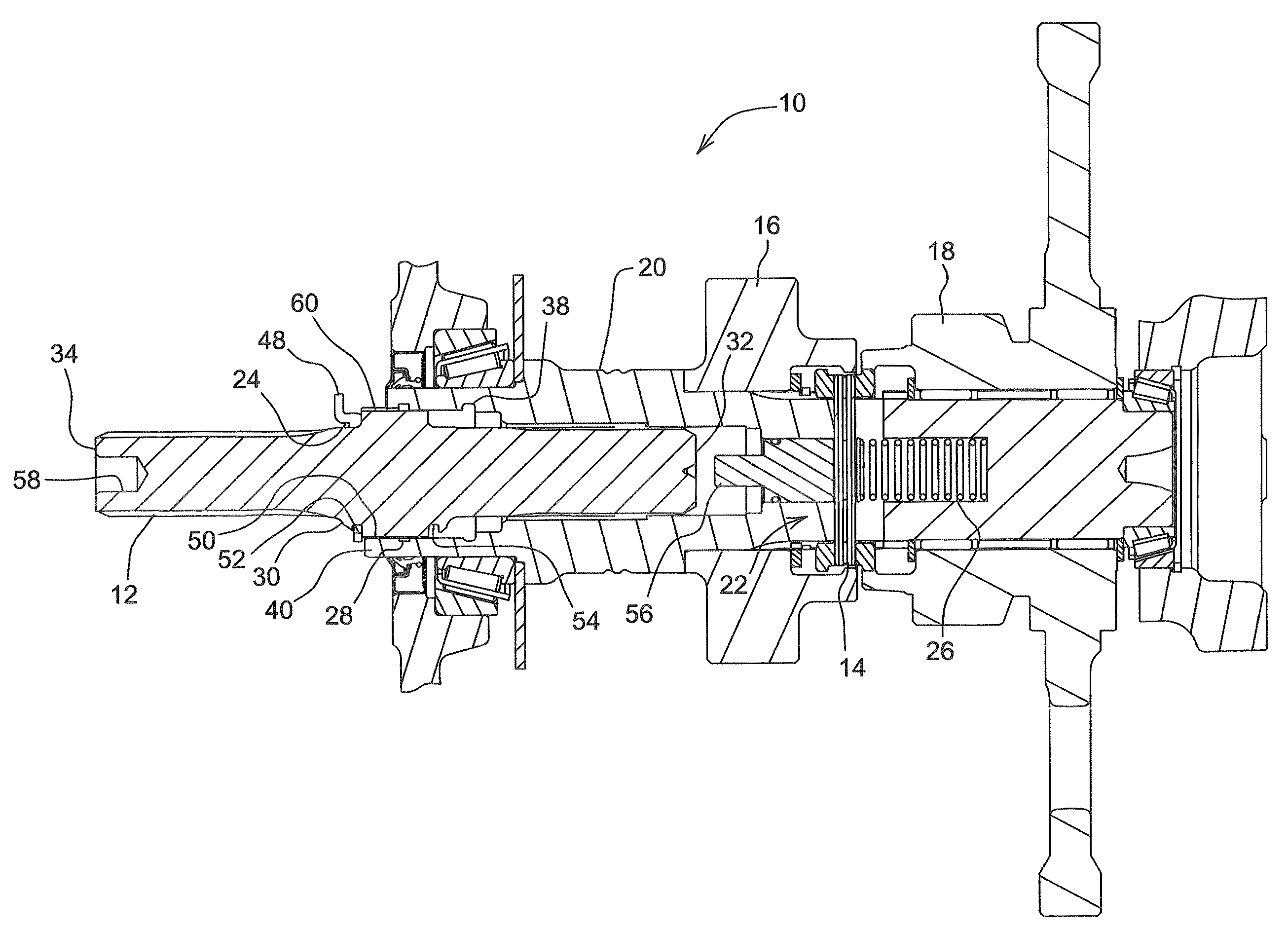
Figure 1 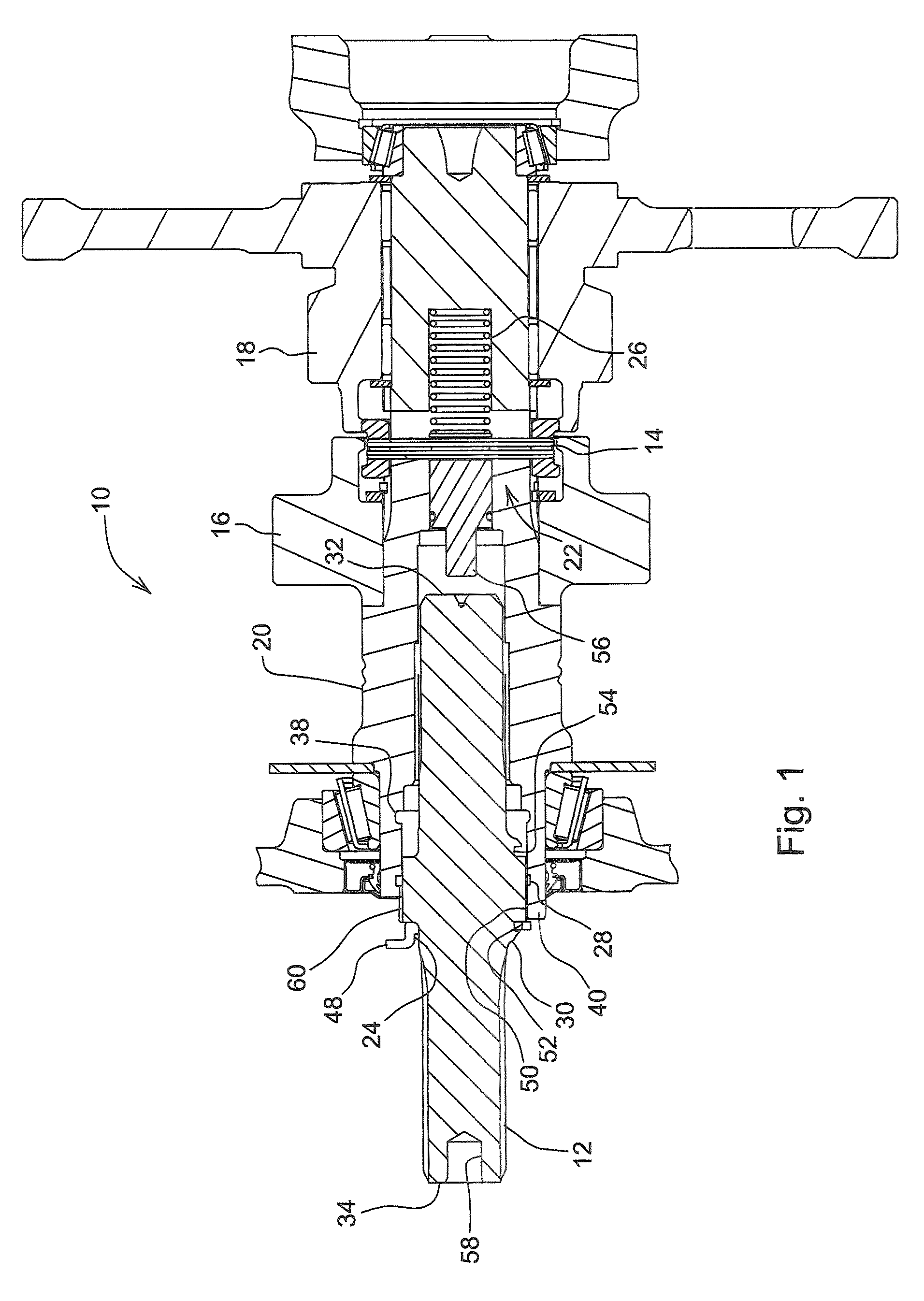
Figure 2 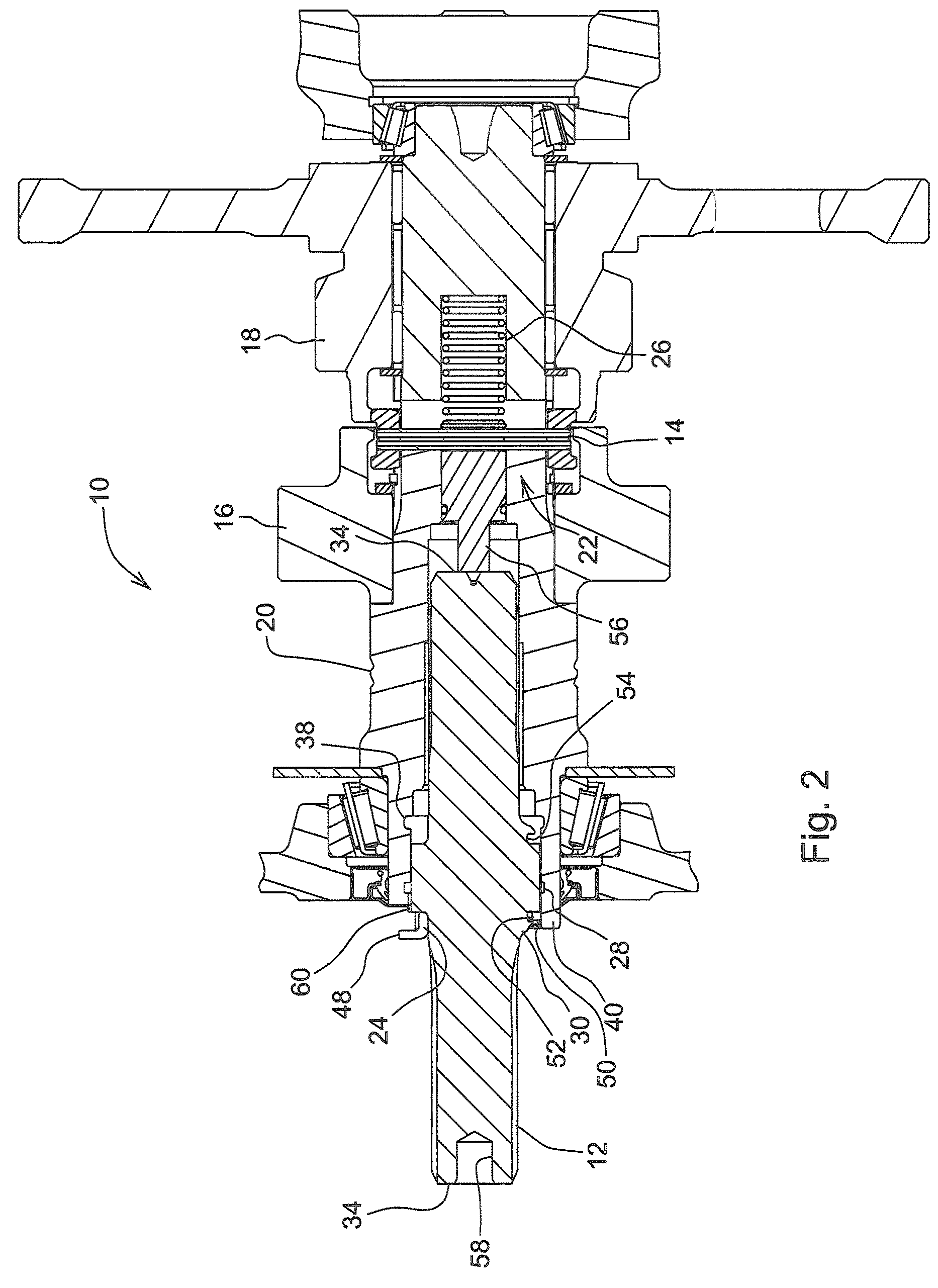
Figure 3
Abstract
Description
FIELD OF THE INVENTION
[0001] The present invention relates generally to a reversible two speed PTO Stub Shaft, and more specifically to an improved PTO Stub Shaft for a cheaper and efficient installation process.BACKGROUND OF THE INVENTION
[0002] Power Take-Off Shafts or PTOs are used on agricultural vehicles such as tractors to provide power from the engine to agricultural implements. As the use of PTOs developed over the years, the industry developed a standard for two speed PTOs comprising gear speeds of 1000 and 540 rpms. Thus in order to accommodate industry standards of a particular implement relative to the appropriate gear speed, it is necessary to provide a power take-off assembly which allows quick and easy installation of a proper PTO assemblies, the output shaft has a internally splined portion adapted to axially receive the externally splined reversible power take off shaft to prevent relative rotational movement between the power take-off stub shaft and output shaft. The ...
Examples
Embodiment Construction
[0015]While the present invention is susceptible of embodiments in various forms, there is shown in the drawings and will hereinafter be described a preferred embodiment of the invention with the understanding that the present disclosure is to be considered as setting forth an exemplification of the invention which is not intended to limit the invention to the specific embodiment illustrated.
[0016]Referring now to the drawings, wherein like reference numerals refer to like parts throughout the several views, there is shown in FIG. 1 a PTO assembly 10. A gear collar 14 is located between a first gear 16 and a second gear 18 and is capable of sliding axially between a first speed and a second speed, respectively 1000 rpm and 540 rpm.
[0017]FIGS. 1-3 show a snap ring 24 fastened around the outer surface of a PTO stub shaft 12. A PTO output shaft 20 has an internal spline 38 and an installation surface 50. The PTO stub shaft 12 has a first recess 52 and an external spline 60, wherein the...