
Blind fastener and method
a blind rivet and fastener technology, applied in the field of blind rivet elements, can solve the problems of unweakened hank wall and available entire wall thickness, and achieve the effect of increasing the length/width ratio
Patent Information
- Authority / Receiving Office
- US · United States
- Patent Type
- Patents(United States)
- Current Assignee / Owner
- Publication Date
- 2011-03-08
Smart Images
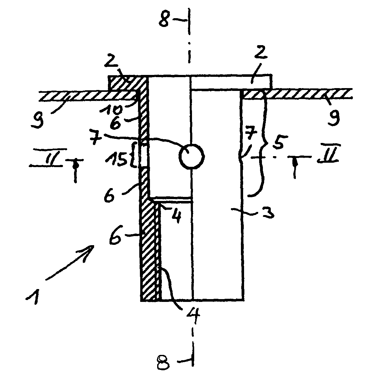
Figure 1 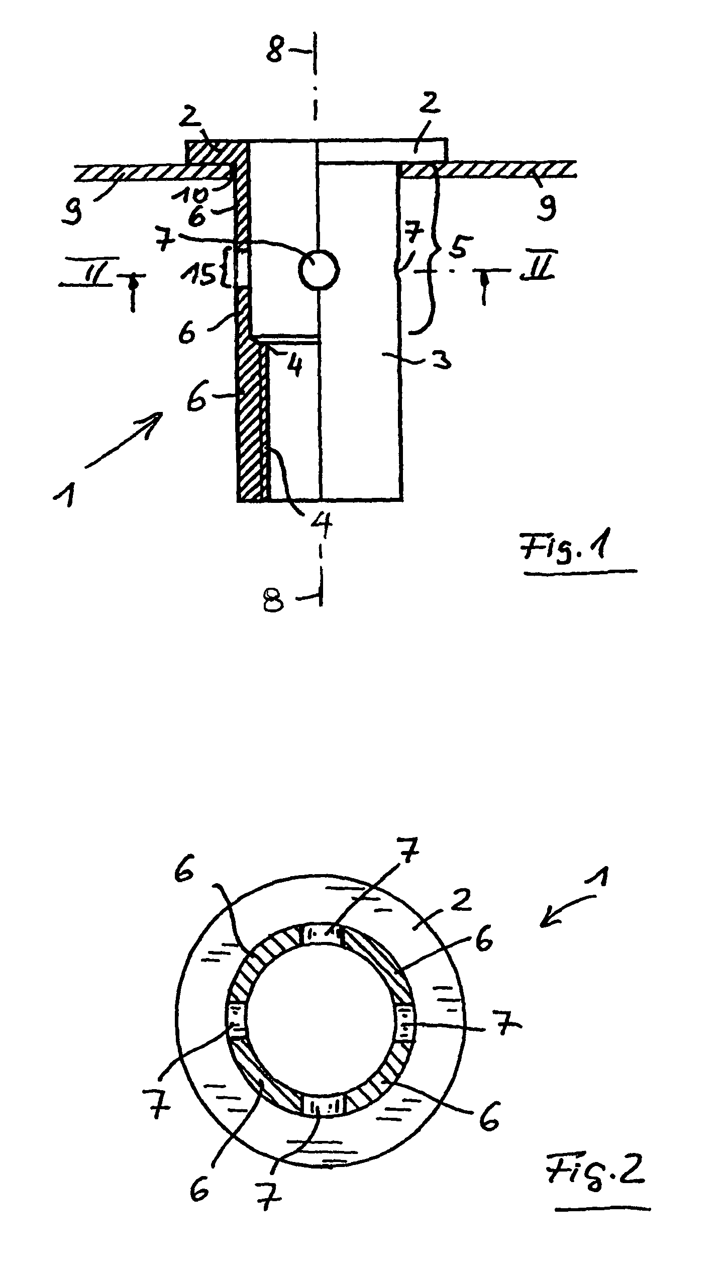
Figure 2 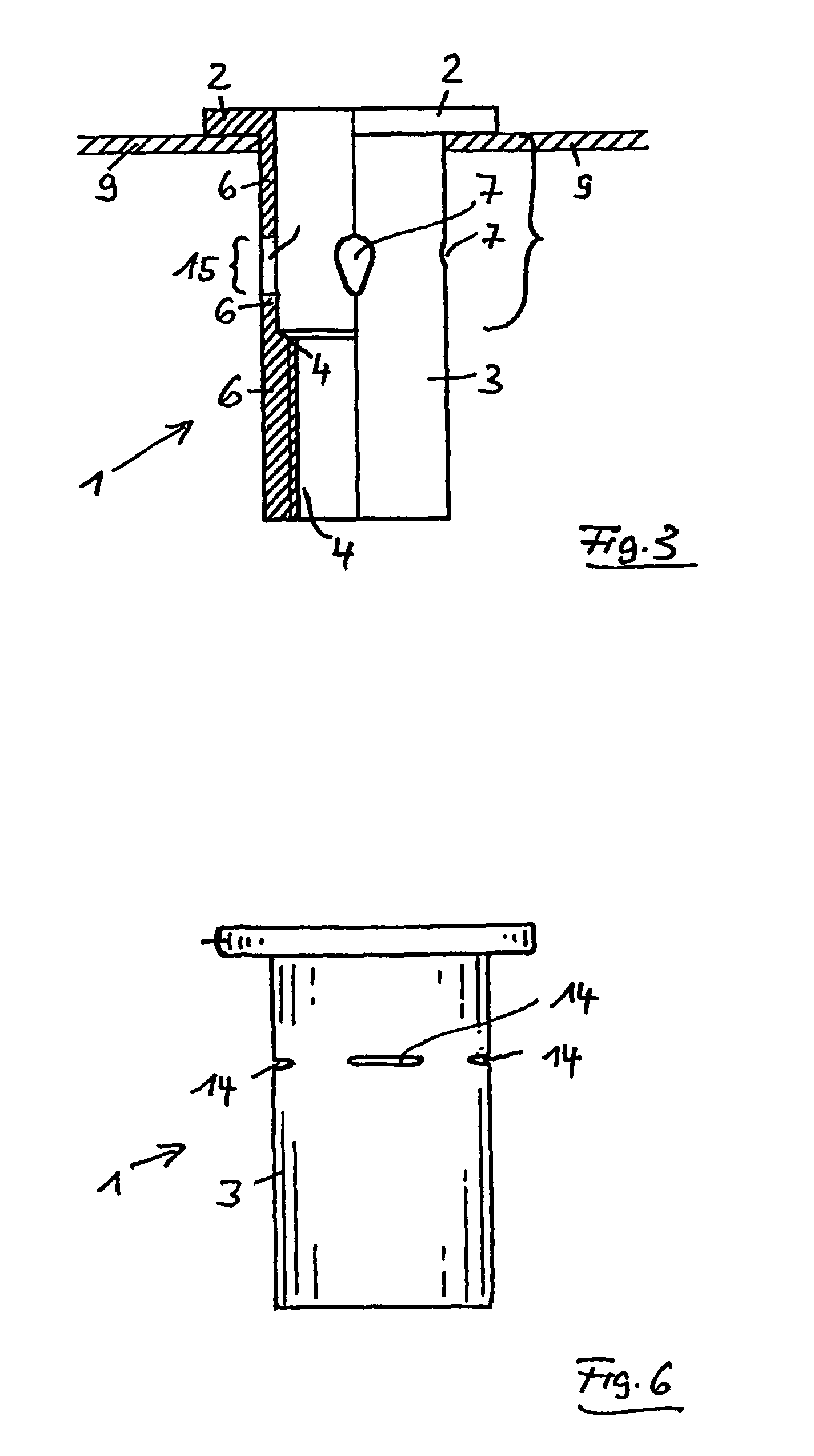
Figure 3
Abstract
Description
CLAIM OF PRIORITYApplicant hereby claims the priority benefits under the provisions of 35 U.S.C. §119, basing said claim of priority on European Patent Application Serial No. 06 022 882.2, filed Nov. 3, 2006 and European Patent Application Serial No. 06 024 927.3, filed Dec. 1, 2006. In accordance with the provisions of 35 U.S.C. §119 and Rule 55(b), certified copies of the above-listed European patent applications will be filed before grant of a patent.BACKGROUND OF THE INVENTIONThe present invention relates to fasteners, and in particular to a blind rivet element with a setting head and a shank. The shank has an internal thread or a receptacle for a threaded bolt at its distal end, and a deformation area between the internal thread or the bolt receptacle. The setting head has a larger outside diameter than the shank. The invention relates, furthermore, to a novel use of a blind rivet element.Blind rivet elements of this type are designed, for example, as a blind rivet nut or a bli...
Examples
first embodiment
FIGS. 1 and 2 illustrate, for the invention, the blind rivet nut 1 before it is set. The blind rivet nut 1 has a setting head 2 and a shank 3. The shank 3 is provided with an internal thread 4 in the region of its distal end or the end facing away from the setting head 2. A deformation portion 5 is positioned between the internal thread 4 and the setting head 2. Basically, the deformation portion 5 extends as far as the setting head 2, since the blind rivet nut 1 could be deformed in this region when a pull is introduced into the internal thread 4. In practice, since the blind rivet nut is to be connected to a plate-shaped component 9, such as metal sheet 9, this deformation portion 5 extends only as far as that side of the metal sheet which faces away from the setting head 2.
The shank 3 has, over the circumference of the shank 3, a weakening of shank wall 6 in a central region of the deformation portion 5. In the embodiment shown in FIGS. 1 and 2, this weakening is formed by four h...
third embodiment
FIG. 6 shows the blind rivet nut 1. It differs from the other two embodiments only in that, in relation to the initial state illustrated for these, instead of the configuration with the four holes 7 of circular or drop-shaped cross section, an arrangement with four slots 14 at a corresponding location is provided. Before the deformation of the deformation portion 5, these four slots14 are therefore already present and, during the setting of the blind rivet nut, are further deformed tangentially, starting from this shape, with the result that the slots 14 are lengthened.
The blind rivet nut 1 according to the embodiment shown in FIG. 7 is modified, as compared with that according to FIGS. 1 and 2, only to the effect that, instead of the holes 7 of circular cross section, holes 7 are provided which are designed as long holes, the longitudinal axis of the long holes running parallel to the longitudinal axis 8 of the shank 3.
The embodiment according to FIG. 8 differs from that according ...