
Device for opposing sloshing in a flexible tank
a flexible tank and sloshing technology, which is applied in the direction of drinking vessels, containers, cosmonautic components, etc., can solve the problems of affecting the balance of the vehicle, affecting the pilot's ability, and causing the liquid to slouch, so as to prevent the liquid from sloshing, reduce the vertical movement of the top cushion, and prevent the first and second ties from being wound out excessively
Patent Information
- Authority / Receiving Office
- US · United States
- Patent Type
- Patents(United States)
- Current Assignee / Owner
- Publication Date
- 2012-03-20
Smart Images
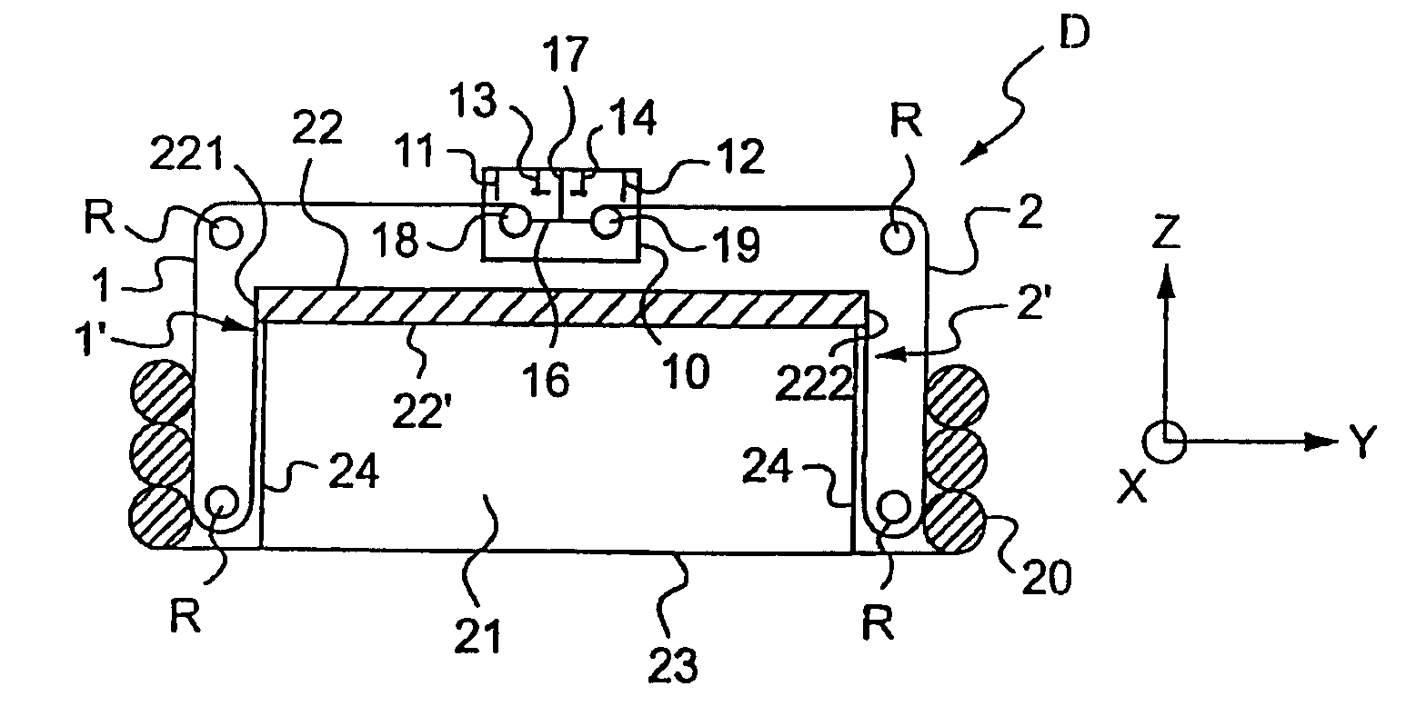
Figure 1 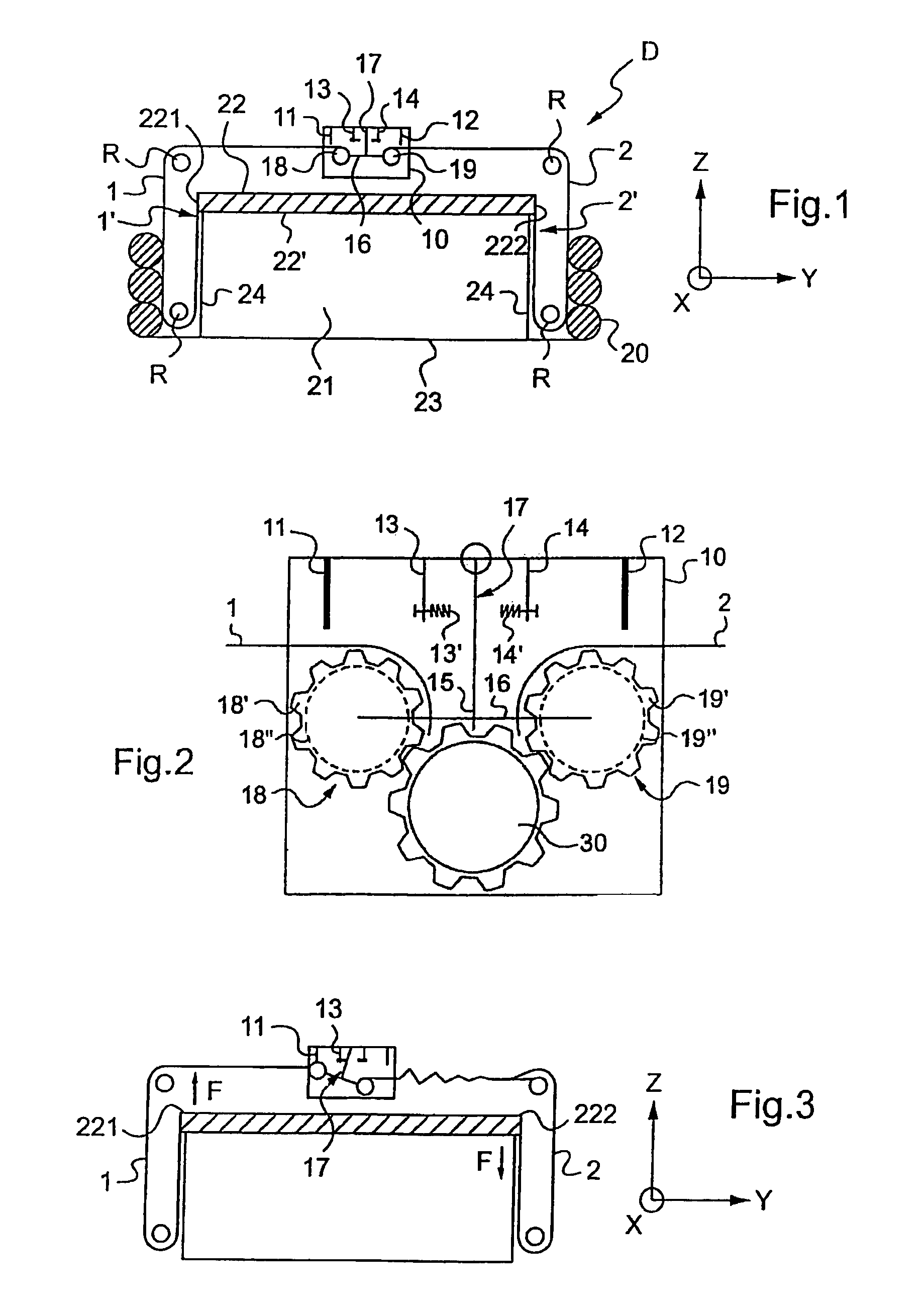
Figure 2 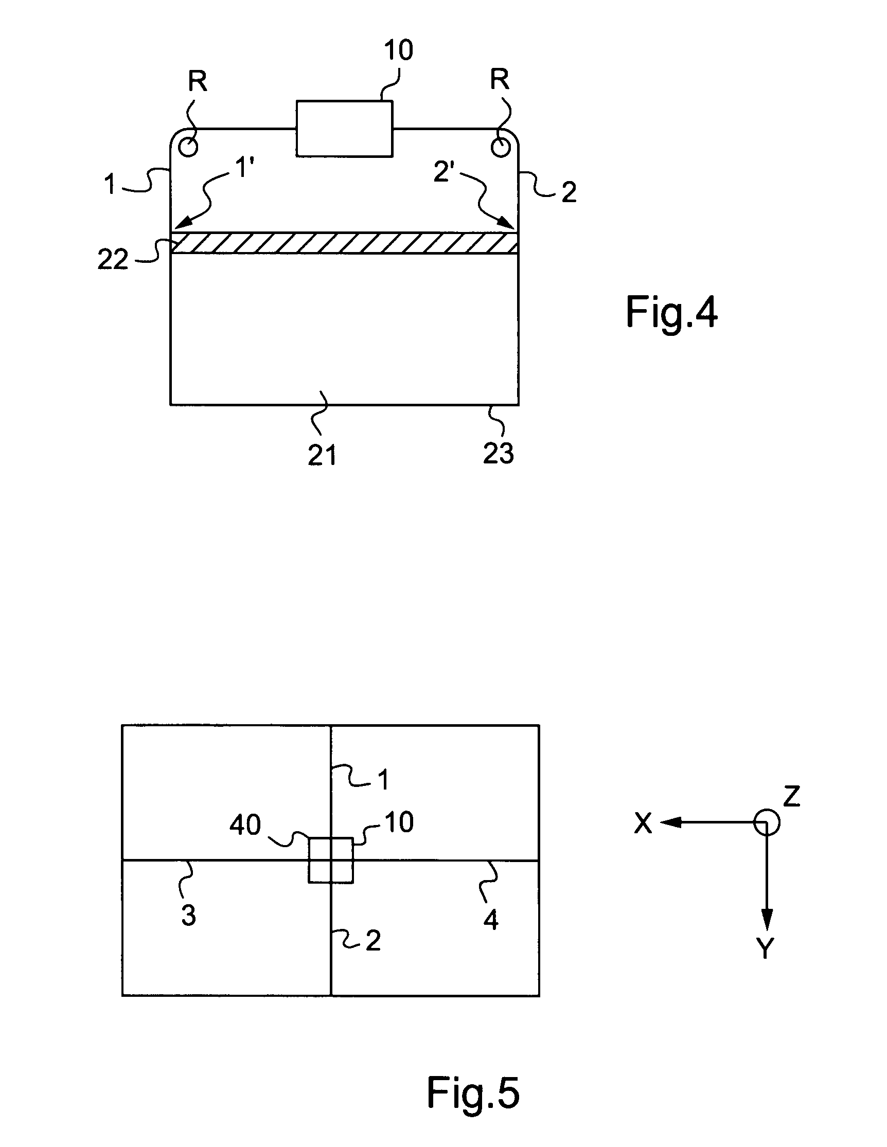
Figure 3
Abstract
Description
[0001] The present invention relates to a device for opposing sloshing in a flexible tank arranged in a vehicle, e.g. a rotorcraft.BACKGROUND OF THE INVENTION
[0002] A flexible tank on board a vehicle may contain kerosene for feeding to a rotorcraft gas turbine engine, for example, or may contain water for fire-fighting if the vehicle is a water-bombing helicopter, in particular.
[0003] When the vehicle moves, the liquid itself moves inside the tank leading to the liquid level rising on one side of the tank and falling on the other side of the tank, resulting in sloshing that can lead to numerous inconveniences. Such sloshing can lead to hammering that might damage the structure of the vehicle, or to a shift in its center of gravity, which is harmful to the balance of the vehicle and makes it difficult to pilot, particularly if it is a helicopter type rotorcraft.
[0004] Document U.S. Pat. No. 6,622,966 discloses a first device having a ballasted float placed on the liquid contained in the ...
Examples
first embodiment
[0057]With reference to FIGS. 1, 3, and 5, in particular, in a first embodiment, the end zones 1′ and 2′ of the first and second ties 1 and 2 are fastened to the top cushion 22, from which top cushion 22 they extend towards the bottom 23 of the tank 1.
second embodiment
[0058]In contrast, with reference to FIG. 4, in a second embodiment, the end zones 1′ and 2′ of the first and second ties 1 and 2 that are fastened to the top cushion 22, leave the top cushion 22 going away from the bottom 23 of the tank 1.
[0059]Furthermore, the deflector means R are optionally also used so that the end zones 1′ and 2′ of the first and second ties1 and 2 are perpendicular to the horizontal surface 22′ of the top cushion 22, said surface facing the bottom 23 of the tank. This disposition significantly increases the effectiveness of the device.
[0060]The surface 22′ is said to be horizontal insofar as it is parallel to the (X,Y) plane of the vehicle which defines the horizontal while the elevation axis Z defines the vertical.
[0061]Each tie 1, 2 has one end zone 1′, 2′ secured to the top cushion 22, while its other end is secured to main distributor means 10.
[0062]The main distributor means comprise blocker means 11, 12, brake means 13, 14, and a pendular support 17 hav...