
Image forming method
a technology of image and forming method, applied in the direction of digital output to print units, instruments, digitally marking record carriers, etc., can solve the problems of not being smooth, not being precise, not being glossy as intended, etc., to prevent the amount of clear toner, prevent the occurrence of moire, and achieve sufficient color saturation
Patent Information
- Authority / Receiving Office
- US · United States
- Patent Type
- Patents(United States)
- Current Assignee / Owner
- Publication Date
- 2015-04-28
Smart Images
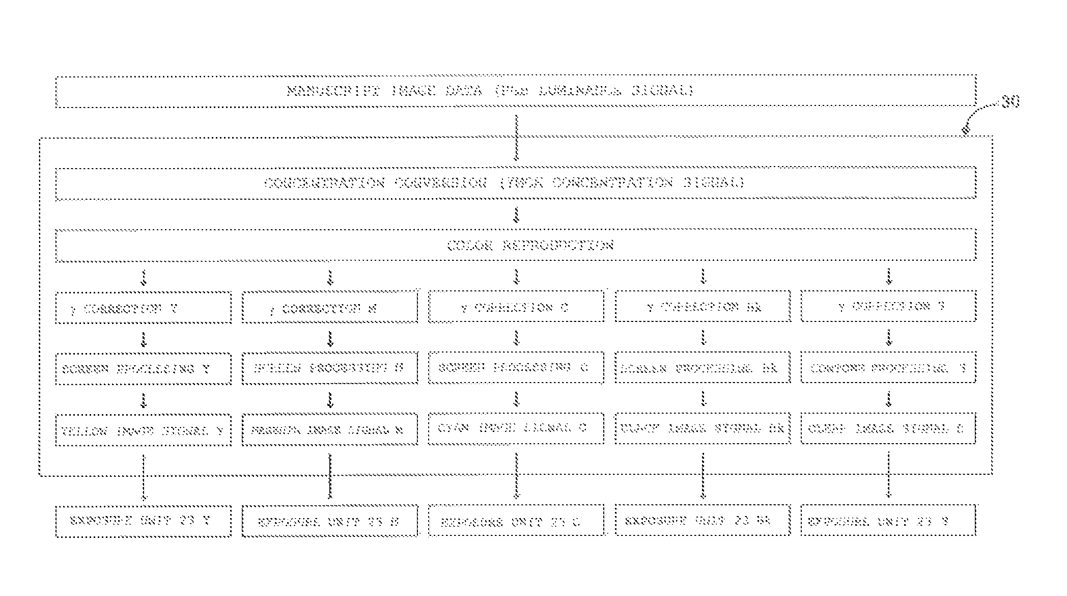
Figure 1 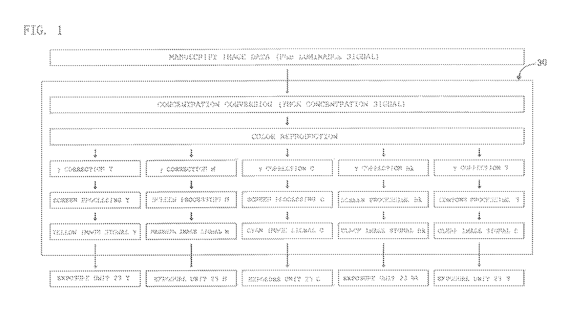
Figure 2 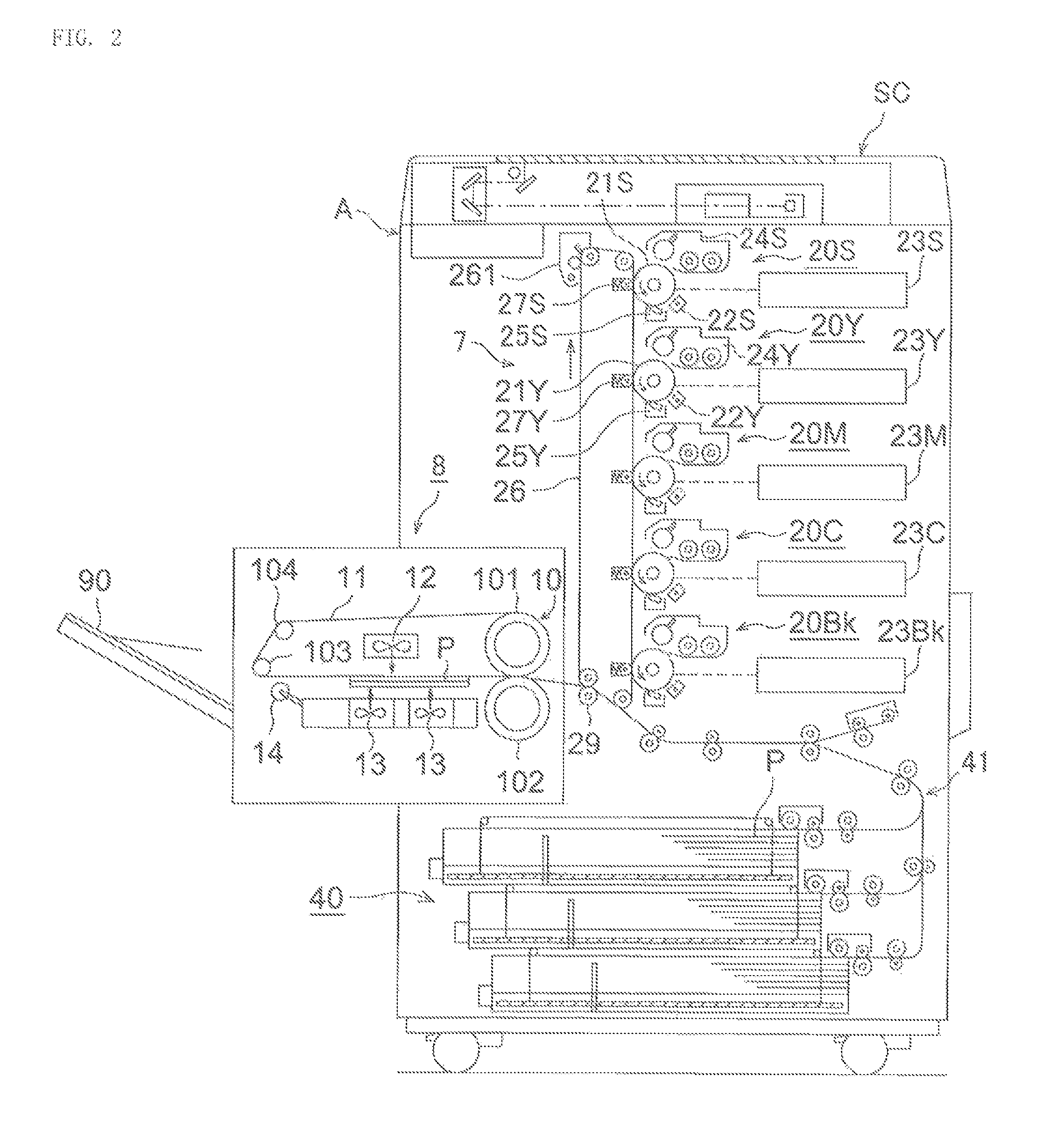
Figure 3
Abstract
Description
CROSS REFERENCE TO RELATED APPLICATION
[0001] This Application claims the priority of Japanese Patent Application No. 2013-061490 filed on Mar. 25, 2013, which is incorporated by reference herein.TECHNICAL FIELD
[0002] The present invention relates to an image forming method which is capable of collectively fixing a color toner image and a clear toner image and then outputting a glossy image.BACKGROUND ART
[0003] The image forcing apparatus of electrophotographic system, for example, a full-color image forming apparatus, provides output typically in a manner such that using toners of three colors, yellow, cyan, and magenta, or toners of four colors with black added to the three colors, dots of each color toner are to rood on an lavage support such as a sheet of papery thereby allowing a full-color image to be visually identified as a whole.
[0004] In an electrophotographic system, halftone images can be formed, for example, according to data obtained by performing screen processing using a ...
Examples
example 1
[0112]The image forming apparatus shown in FIG. 2 was used to form, on a sheet of ordinary paper, a test image [1] having image regions A to B with varying densities in magenta in one image as shown in FIG. 3(a). At this time, the magenta toner image was formed in accordance with a magenta image signal obtained through the screen processing using a dot screen pattern having a screen line count of 190 lpi. Furthermore, the clear toner image was formed in accordance with a clear image signal obtained through the contone processing. The clear image signal is assumed to have been controlled so that the total amount (the pre-set amount) of (the adhered magenta toner+the adhered clear toner) was 10 g / m2.
[0113]In the test image shown in FIG. 3(a), the numerical value in each image region indicates the amount of adhered magenta toner.
example 2
[0114]The image forming apparatus shown in FIG. 2 was used to form, on a sheet of ordinary paper, a test image [2] having image regions A to D with varying densities in magenta and cyan in one image as shown in FIG. 3(b). At this time, the magenta toner image and the cyan toner image were formed in accordance with a magenta image signal and a cyan image signal obtained through the screen processing using a dot screen pattern having a screen line count of 190 lpi. Furthermore, the clear toner image was formed in accordance with a clear image signal obtained through the contone processing. The clear image signal is assumed to have been controlled so that the total amount (the pre-set amount) of (the adhered magenta toner+the adhered cyan toner+the adhered clear toner) was 10 g / m2.
[0115]In the test image shown in FIG. 3(b), the upper numerical value in each image region indicates the amount of adhered magenta toner, while the lower numerical value indicates the amount of adhered cyan t...
example 3
[0116]A test image [3] was formed in the same manner as in Example 1 except that the magenta toner image was formed using a screen pattern having a screen line count of 270 lpi in Example 1.