
Electrical receptacle connector
a technology of electric receptacles and connectors, which is applied in the direction of coupling devices, two-part coupling devices, electrical apparatus, etc., can solve the problems of increasing the possibility that various electronic components in the device will suffer from electromagnetic interference (emi) or radio frequency interference (rfi), and the high speed electrical transmission in these devices can produce electromagnetic emissions. , to reduce the spacing, reduce the ground resistance, and improve the securing force
Patent Information
- Authority / Receiving Office
- US · United States
- Patent Type
- Patents(United States)
- Current Assignee / Owner
- Publication Date
- 2017-01-03
Smart Images
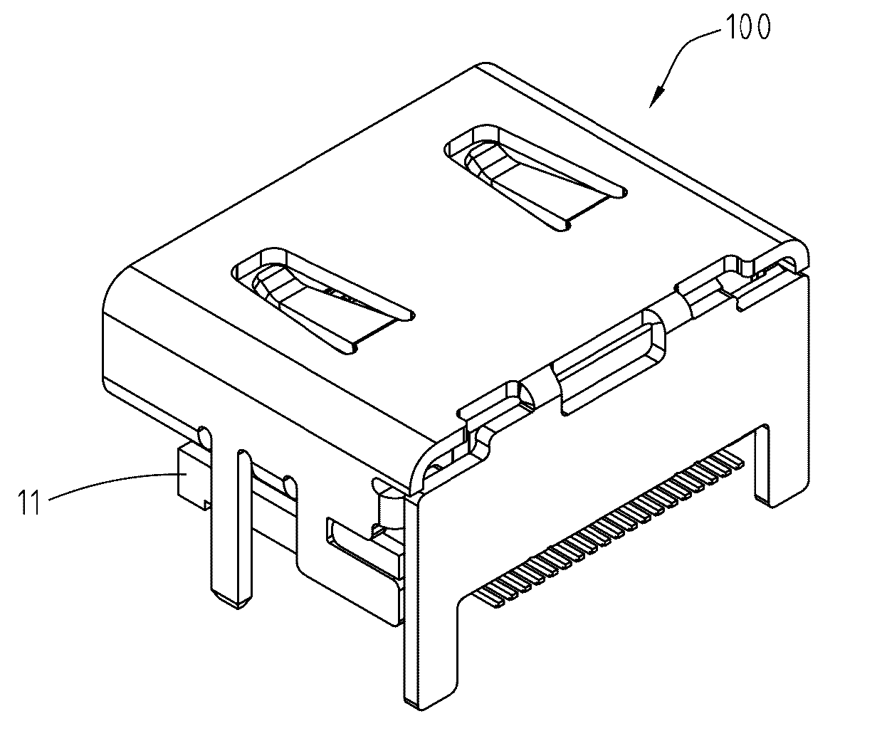
Figure 1 
Figure 2 
Figure 3
Abstract
Description
CROSS-REFERENCES TO RELATED APPLICATIONS
[0001] This non-provisional application claims priority under 35 U.S.C. §119(a) on Patent Application No. 103208993 and 104105188, filed in Taiwan, R.O.C. on 2014 May 22 and 2015 Feb. 13, the entire contents of which are hereby incorporated by reference.FIELD OF THE INVENTION
[0002] The instant disclosure relates to an electrical connector, and more particularly to an electrical receptacle connector.BACKGROUND
[0003] Currently, the increase in the functionality of various electronic devices is driving the demand for smaller and smaller devices that are easier and more convenient for users to carry and use. This causes many electrical / electronic components within the device to be located closer together. This increases the possibility that the various electronic components in the device will suffer from electromagnetic interference (EMI) or radio frequency interference (RFI) either from RF components such as the antenna, microphone components, RF po...
Examples
Embodiment Construction
[0025]Please refer to FIG. 3, FIG. 4, and FIG. 5, illustrating an exemplary embodiment of an electrical receptacle connector 100 according to the instant disclosure. FIG. 3 illustrates a perspective view of the electrical receptacle connector 100. FIG. 4 illustrates an exploded view of the electrical receptacle connector 100. FIG. 5 is a schematic view of EMI analysis for the electrical receptacle connector 100. Here, the electrical receptacle connector 100 may be of a Type-C USB connection interface specification (as shown in FIG. 6). In this embodiment, the electrical receptacle connector 100 comprises an insulated housing 11, a plurality of receptacle terminals 21, and a metallic shell 31.
[0026]Please refer to FIG. 4 and FIG. 5, in which the insulated housing 11 is an elongate member, and the insulated housing 11 comprises a base portion 111 and a tongue portion 112. Here, the base portion 111 and the tongue portion 112 are formed by insert-molding technique, and the tongue porti...