Auxiliary rolling device with magnetic belt

A coiler and magnetic technology, applied in metal rolling, manufacturing tools, metal processing equipment and other directions, can solve problems such as unfavorable coiling, thin strips are not easy to coil, increase the uncontrolled length of the lead head, etc., to shorten the distance, The effect of reducing the occupied length

Active Publication Date: 2017-09-05
CERI TECH +1
View PDF7 Cites 0 Cited by
  • Summary
  • Abstract
  • Description
  • Claims
  • Application Information

AI Technical Summary

Problems solved by technology

The swing-type winding aid is relatively short from the center of the reel, but because the distance between the flying shear and the reel is relatively close, generally no magnetic belt is arranged, but with the increase of rolling speed and slitting speed, the thin strip is not easy to guide Coiler realizes coiling
[0005] Moreover, in the prior art, the magnetic belt and the winder are mostly arranged separately, which requires a separate fixed hinge point for the swing of the magnetic belt, and the magnetic belt often requires a separate base and drive, which will increase the size of the center of the flying shear. Distance from center of double coiler
[0006] In addition, although there are winding aids integrated with magnetic belts in the prior art, the swing-type winding aids equipped with magnetic belts in the prior art often have problems with the center distance of flying shears due to the unreasonable setting of the hinge point of the swing mechanism. The center of the reel is far away, which increases the uncontrolled length of the tape head under high-speed transportation, which is not conducive to the smooth progress of coiling

Method used


Image

  • Auxiliary rolling device with magnetic belt
  • Auxiliary rolling device with magnetic belt
  • Auxiliary rolling device with magnetic belt

Examples


Embodiment Construction

[0055] The details of the present invention can be understood more clearly with reference to the accompanying drawings and the description of specific embodiments of the present invention. However, the specific embodiments of the present invention described here are only for the purpose of explaining the present invention, and should not be construed as limiting the present invention in any way. Under the teaching of the present invention, the skilled person can conceive any possible modification based on the present invention, and these should be regarded as belonging to the scope of the present invention.

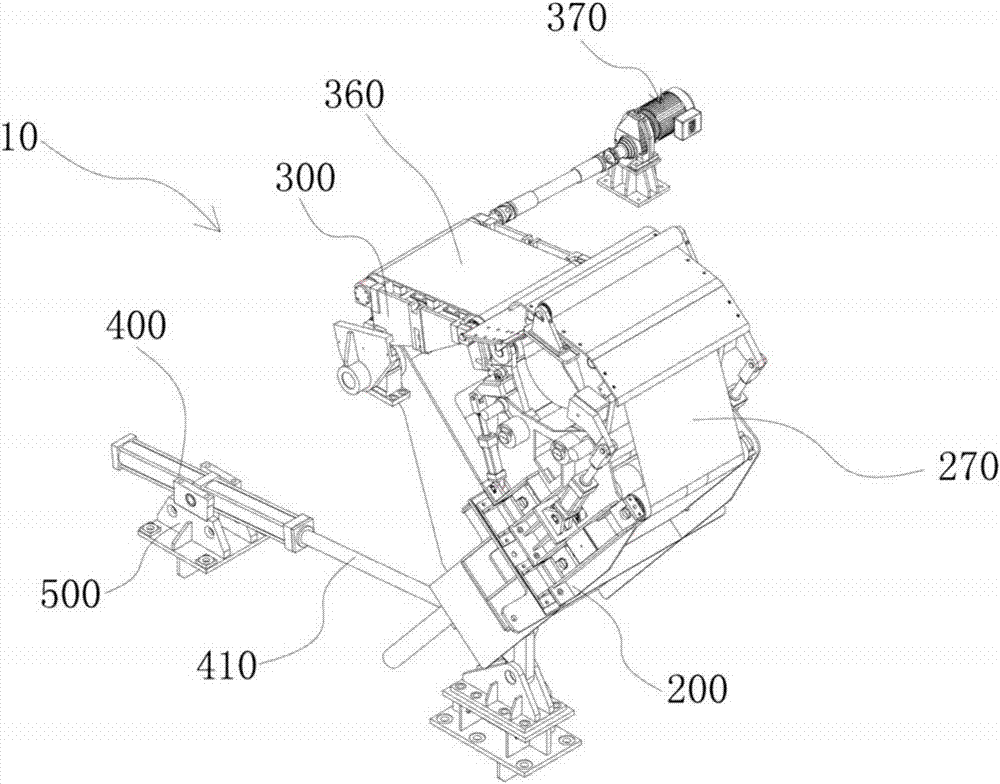
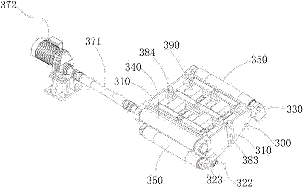
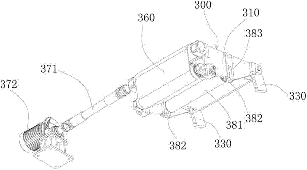
[0056] Please refer to Figure 1 to Figure 8 , the present invention proposes a winding aid 10 with a magnetic belt, the winding aid 10 with a magnetic belt at least includes a rotating shaft 100, a winding aid frame 200 and a magnetic belt frame 300, the rotating shaft 100 is arranged horizontally, and the winding aid The frame body 200 is V-shaped with an upward openin...


PUM


Abstract

The invention provides an auxiliary rolling device with a magnetic belt and relates to a cold continuous rolling production line. The auxiliary rolling device with the magnetic belt at least comprises a rotating shaft, an auxiliary rolling device frame body and a magnetic belt frame body. The rotating shaft is horizontally arranged. The auxiliary rolling device frame body is in a V shape with an upward opening. One top end of the auxiliary rolling device frame body and the rotating shaft are hinged to form a connection end. The other top end of the auxiliary rolling device frame body is rotated around the axis of the rotating shaft to form a free end. The free end is provided with a lower swing arm assembly and an upper swing arm assembly. One end of the magnetic belt frame body is hinged to the rotating shaft in a sliding mode. The other end of the magnetic belt frame body is hinged to the lower swing arm assembly. According to the auxiliary rolling device with the magnetic belt, the whole occupied length is reduced, and the distance between a flying shear center and the center of a dual-reel reeling machine is shortened.

Description

technical field [0001] The invention relates to a cold continuous rolling production line, in particular to a double-drum coiler, in particular to a coiling aid with a magnetic belt for the dual-drum coiler. Background technique [0002] At present, domestic cold rolling coilers mostly use double-drum coilers, which generally need to work together with coil aids, and use coil aids to assist strip steel winding on the drums. With the further increase of the rolling speed, for the cold-rolled products of the tinplate base material with the strip thickness of 0.16-0.18mm, after the strip steel is cut by high-speed flying shear, in order to effectively ensure that the strip steel can be guided for coiling, the A magnetic belt needs to be added at the exit of the six-high rolling mill. [0003] The existing rolling mill export coiling equipment mainly has the following technical problems: [0004] At present, commonly used belt roll aids can be divided into walking lift type ro...

Claims


Application Information

Patent Timeline
Patent Type & Authority Applications(China)
IPC IPC(8): B21B15/00
CPCB21B15/00B21B2015/0014B21B2015/0057
Inventor 米楠李韶岗张海东贾大朋
Owner CERI TECH
Why Eureka
Try Eureka