Industrial automatic roller drying device

An industrial automation, drum drying technology, applied in the direction of drying gas arrangement, drying solid materials, drying goods processing, etc., can solve the problems of slow drying speed of materials, energy waste, insufficient drying, etc., to reduce the possibility of heat deterioration, reduce Energy waste, the effect of improving the drying effect

Inactive Publication Date: 2018-03-13
江苏当升智能装备科技有限公司
View PDF0 Cites 5 Cited by
  • Summary
  • Abstract
  • Description
  • Claims
  • Application Information

AI Technical Summary

Problems solved by technology

[0003] The traditional drying treatment of wet granular materials is generally to place the materials on a drying plate, and then heat them under the drying plate through electric heating wires to make them take away the moisture of the materials to achieve the purpose of drying, but the static parts of the materials Heating and uneven air flow lead to slow drying of materials, insufficient drying, and low energy utilization, resulting in energy waste, and the traditional heating method is unstable due to temperature control, direct contact between materials and heat sources can deliberately lead to shelf life of food materials shorten or even deteriorate, therefore, an industrial automatic drum drying device is proposed to address the above problems

Method used


Image

  • Industrial automatic roller drying device
  • Industrial automatic roller drying device

Examples


Embodiment Construction

[0019] The following will clearly and completely describe the technical solutions in the embodiments of the present invention with reference to the accompanying drawings in the embodiments of the present invention. Obviously, the described embodiments are only some, not all, embodiments of the present invention. Based on the embodiments of the present invention, all other embodiments obtained by persons of ordinary skill in the art without making creative efforts belong to the protection scope of the present invention.

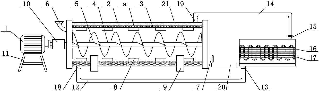
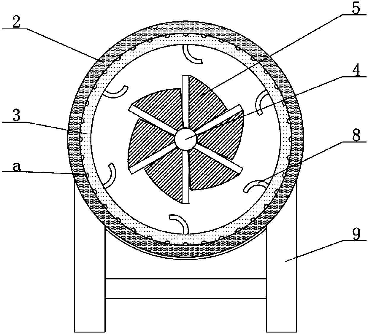
[0020] see Figure 1-2 , the present invention provides a technical solution:

[0021] An industrial automatic drum drying device, comprising a motor 1 and a drying drum 21, a heat exchange device is provided on the right side of the drying drum 21, and the heat exchange device includes an air inlet 15, an air outlet 13, a heat exchange tube 16 and a heat dissipation device. Sheet 17, the drying drum 21 includes an outer cylinder 2 and an inner cylinder 3, th...


PUM


Abstract

The invention relates to the technical field of drying equipment, in particular to an industrial automatic roller drying device which comprises a motor and a drying roller. A heat exchange device is arranged on the right of the drying roller, the drying roller comprises an outer barrel body and an inner barrel body which are in sliding connection, the surface of the inner barrel body is provided with air holes, multiple shovelling plates are fixedly arranged on the wall of the inner barrel body, a horizontal rotating shaft is arranged in the inner barrel body, a spiral blade is fixedly arranged on the surface of the rotating shaft, a base is fixedly connected to the bottom end of the drying roller, a speed reducer is fixedly arranged at the tail end of a main shaft of the motor, the rightend of the rotating shaft is fixedly connected with the right wall of the inner barrel body, and the left end of the rotating shaft penetrates through the left wall of the drying roller to be fixedlyconnected to an output shaft of the speed reducer. By means of the industrial automatic roller drying device, particular materials can be dried in a closed mode, dust flying is avoided, the machiningenvironment is not affected, drying is thorough, the energy utilization rate is high, dried good granules are not crushed in the drying process, and the device is worthy of being popularized.

Description

technical field [0001] The invention relates to the technical field of drying equipment, in particular to an industrial automatic drum drying device. Background technique [0002] Drying equipment, also known as dryers and dryers, is equipment used for drying operations. The moisture in the material (generally refers to moisture or other volatile liquid components) is vaporized and escaped by heating to obtain a solid with a specified moisture content. For materials, the purpose of drying is to meet the needs of material use or further processing. In addition, the dried materials are also convenient for transportation and storage. For example, drying the harvested grains below a certain moisture content to prevent mildew, because natural drying is far from meeting the needs of production. In order to meet the needs of development, various mechanized dryers are more and more widely used, so the demand for drying equipment is increasing. [0003] The traditional drying treatm...

Claims


Application Information

Patent Timeline
Patent Type & Authority Applications(China)
IPC IPC(8): F26B11/14F26B21/04F26B25/00F26B25/04F26B25/16
CPCF26B11/14F26B21/04F26B25/003F26B25/04F26B25/16
Inventor 王君
Owner 江苏当升智能装备科技有限公司
Why Eureka
Try Eureka