Alternator device

a technology of alternator and rotor body, which is applied in the direction of magnetic circuit rotating parts, stator/rotor bodies, magnetic circuit shape/form/construction, etc., can solve the problems of mechanical energy input not being efficiently converted into another useful form of energy, loss of energy, etc., and achieves the effect of generating electricity, facilitating rotation of alternators, and reducing energy consumption

Active Publication Date: 2016-11-17
ALMARRI SALEM SAQR MAJED BIN SAQR
View PDF6 Cites 3 Cited by
  • Summary
  • Abstract
  • Description
  • Claims
  • Application Information

AI Technical Summary

Benefits of technology

[0011]A alternator device and a method for converting mechanical energy into electrical energy are disclosed by the present invention. The present alternator device works on the principle of magnetization. The present alternator device converts mechanical energy into electrical energy by mechanically rotating a plurality of rotating disks comprising coil ducts around a magnet of the alternator device. The rotating disks are not in physical contact between each other. The rotating disks comprising the coil ducts are positioned in such a manner that each rotating disk is magnetized by a single pole (North or South) of the magnet. The alternator device of this invention does not need electromagnetic energy to turn the alternator. Motion energy can be used to turn the alternator. A human being can easily rotate the alternator and generate electricity. This is of a great application to wind turbines for example.
[0012]According to an embodiment of the invention, the device is adapted to create a magnetic field with minimum amount of energy required to rotate the rotating disks without need of electromagnetic energy and operate the device for the production of electrical energy from mechanical energy. This is partially due to the absence of physical contact between the magnetized disks. According to an embodiment of the invention, the device is adapted to be a very simple alternator device without brushes and hence requires minimum maintenance. According to an embodiment of the invention, the device is adapted to produce continuous electricity from the magnetic field inside the conventional alternator device and to store the electrical energy inside an energy storage unit such as a battery and / or to operate electrical components. The device can be adapted to be connected to a wind turbine for rotating the magnetized disks and operating the device. According to an embodiment of the invention, the device is adapted to produce negligible noise during operation due to the non-contact of the magnetic disks between them during operation.

Problems solved by technology

However, such conversion is not always hundred percent efficient and there is always a loss of energy during the conversion process.
However, due to lack of efficient devices and methods such mechanical energy input cannot be converted efficiently into another useful form of energy.
Traditional solutions do provide a way for conversion of mechanical energy into electrical energy, but still have limitations.
These limitations are based on sources of mechanical energy, loss of energy during conversion, compactness, installation and the like.
A disadvantage of traditional alternators is the energy loss due to the contact between the magnetized disks and / or coil ducts.
Another disadvantage of traditional alternators is the loss of energy due to the dual pole magnetization (North and South) of a same magnetized disk / coil duct during operation.
Also, traditional alternators have N / S alternating members which results in magnetizing the fixed magnet, so it is difficult to turn the alternator.

Method used


Image

  • Alternator device
  • Alternator device
  • Alternator device

Examples


Embodiment Construction

[0054]The exemplary embodiments described herein detail for illustrative purposes are subjected to many variations. It should be emphasized, however, that the present invention is not limited to alternator device and method for converting mechanical energy into electrical energy. It is understood that various omissions and substitutions of equivalents are contemplated as circumstances may suggest or render expedient, but these are intended to cover the application or implementation without departing from the spirit or scope of the present invention.

[0055]The terms “a” and “an” herein do not denote a limitation of quantity, but rather denote the presence of at least one of the referenced item.

[0056]The terms “having”, “comprising”, “including”, and variations thereof signify the presence of a component.

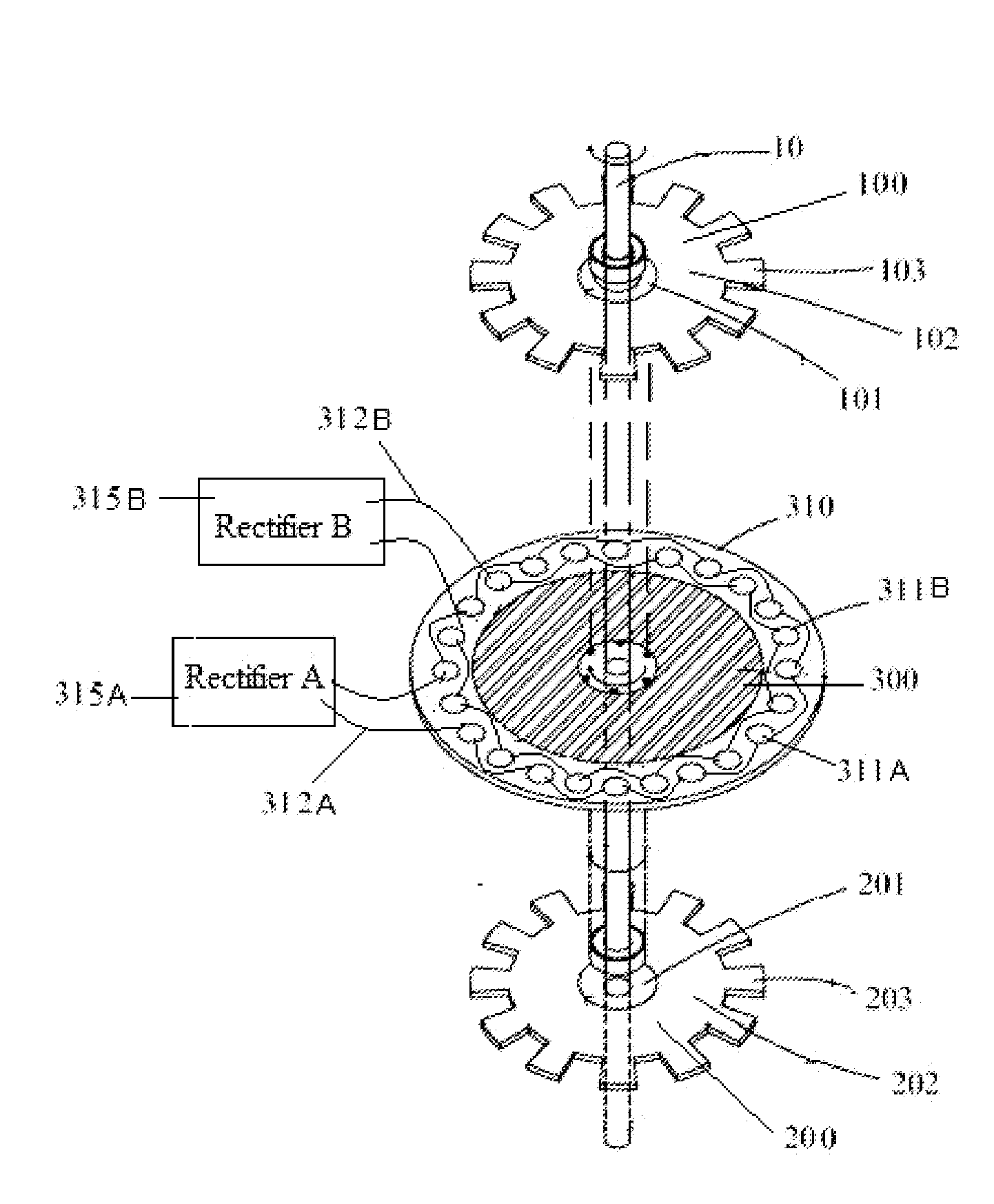
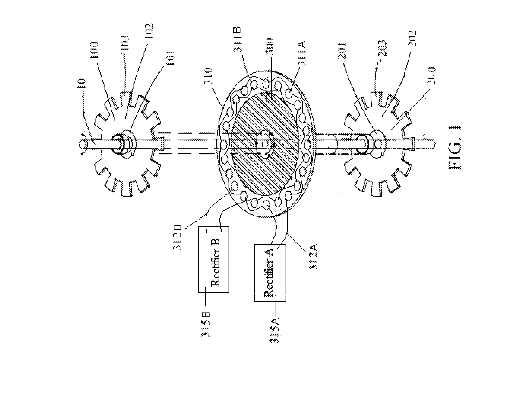
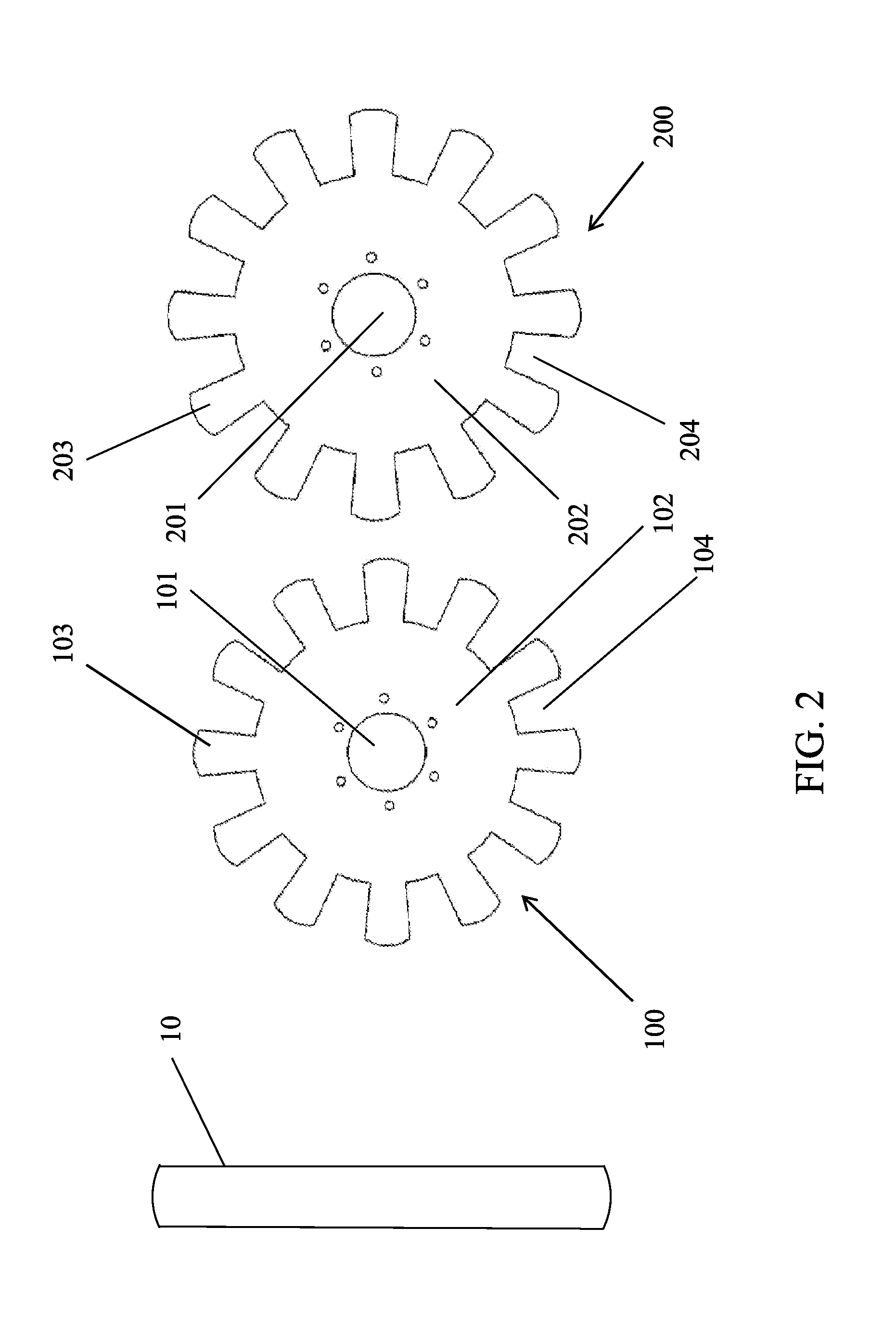
[0057]The present invention provides a alternator device and a method for converting mechanical energy into electrical energy. As described herein the term mechanical energy comprises ...


PUM


Abstract

An alternator device for converting mechanical energy into electrical energy, including first rotating disk comprising first coils ducts; second rotating disk including second coil ducts; a magnet located intermediate the first and second rotating disks to generate first magnetic field having first magnetic pole at the first coil ducts and second magnetic field having second magnetic pole opposite the first magnetic pole at the second coil ducts; and a coil base intermediate the first and second rotating disks, the coil base to receive coils aligned with the first and second coil ducts; wherein the first and second rotating disks are adapted to rotate along a rotation axis while the magnet and the coil base remain in static position, rotation of the rotating disks enabling a rotational movement of the magnetic fields through the coils for generation of electric current within the coils, and a method of manufacturing such device.

Description

FIELD OF THE INVENTION[0001]The present invention relates to the field of energy conversion from mechanical / motional energy into electrical energy. More particularly, the present invention provides an improved alternator device for converting mechanical / motional energy into electrical energy.BACKGROUND OF THE INVENTION[0002]In this technologically running world, energy is essential for each and every system or machine to work. Energy can be of any type, for example heat energy, electrical energy, mechanical energy, chemical energy, and the like.[0003]As we all know, energy can neither be created nor be destroyed, it can be converted from one form to another form. So, the energy conversion field has always been the subject of invention. The invention in energy conversion field takes place very frequently, at the same time it has never been easy to invent any device or method for converting one form of energy to another form of energy. It is already known through the study of thermody...

Claims


Application Information

Patent Timeline
Patent Type & Authority Applications(United States)
IPC IPC(8): H02K1/22H02K11/33H02K15/02F03D9/00H02K11/04
CPCH02K1/22F03D9/002H02K11/33H02K15/02H02K11/046H02K21/44Y02E10/72F03D9/25H02K11/042
Inventor AL MARRI, SAQR MAJED SAQR
Owner ALMARRI SALEM SAQR MAJED BIN SAQR
Why Eureka
Try Eureka