

Method and apparatus for splicing a web material
- Summary
- Abstract
- Description
- Claims
- Application Information
AI Technical Summary
Benefits of technology
Problems solved by technology
Method used
Image

Examples
example 1
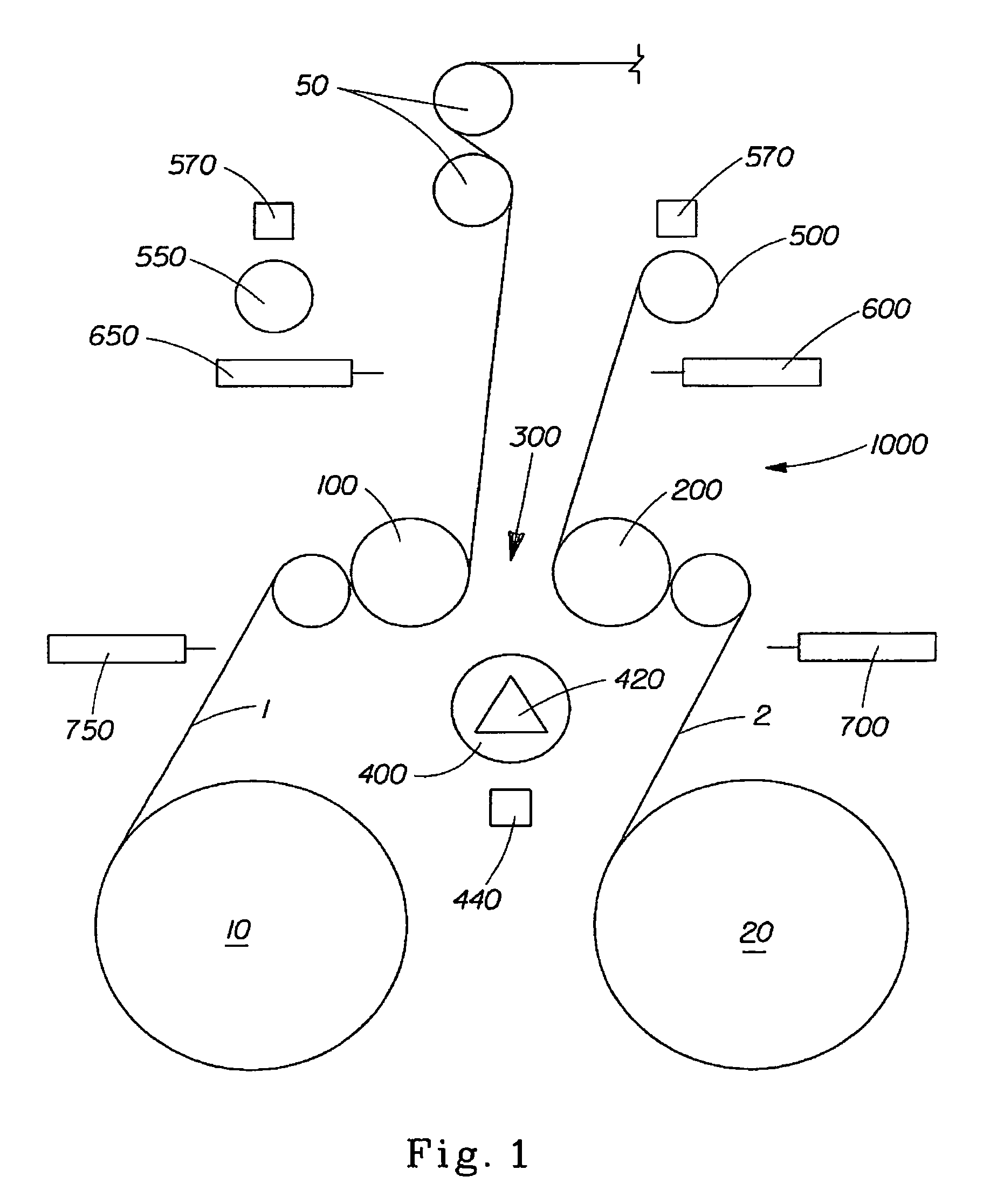
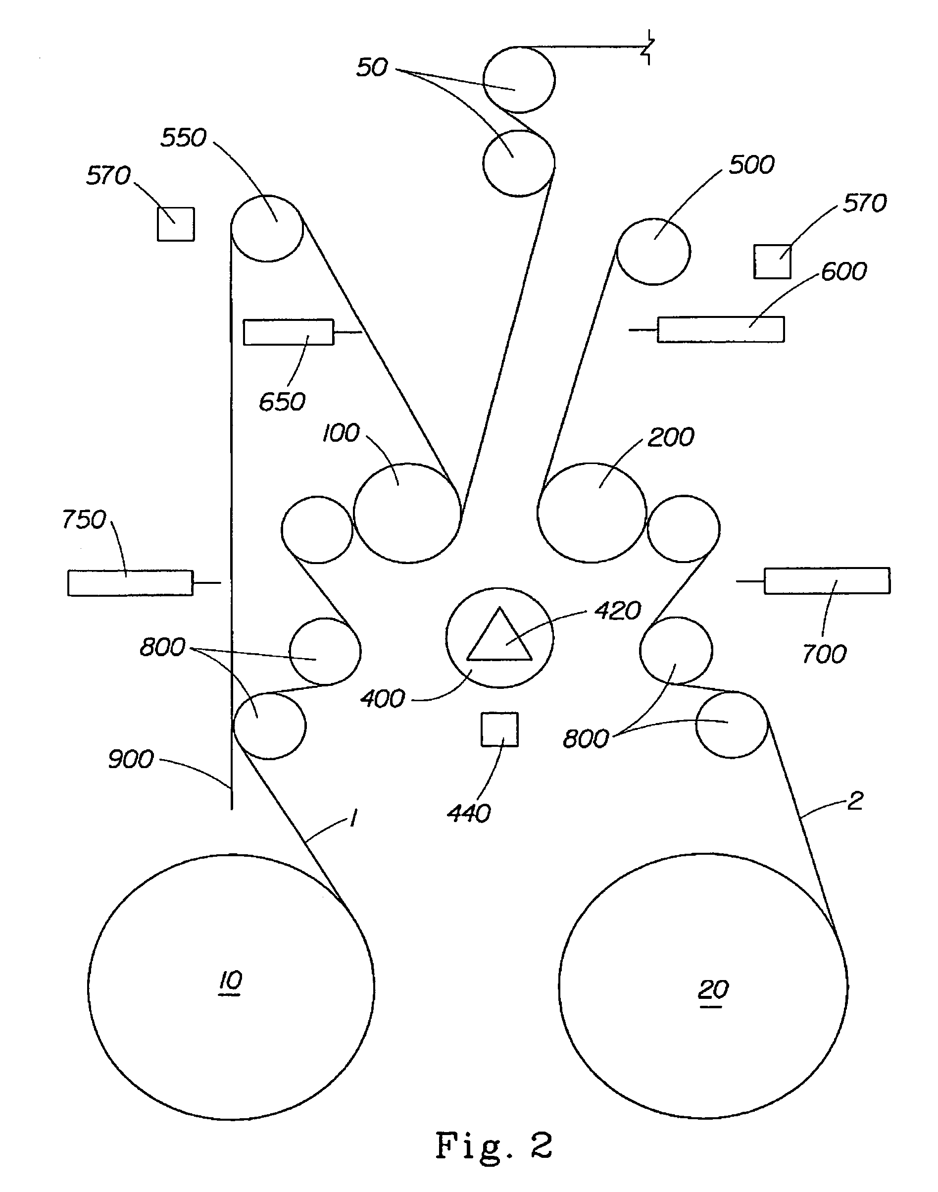
[0060]A first supply roll of first paper towel substrate with a diameter of about 100 inches (254 cm) and a width of about 102 inches (260 cm) is placed upon a first unwind station with the winding axis of the supply roll in a vertical orientation. A portion of the leading edge of the substrate of the first supply roll is releasably attached to a first thread up belt. The thread up belt is routed to carry the first paper towel substrate through the splicing apparatus. The drive motor for the thread up belt is actuated and the belt carries the leading edge of the first paper towel substrate through the splicing apparatus as the fist unwind station rotates the first supply roll. The paper towel substrate is routed through a first pair of s-wrap rollers, past a first upstream web cutter, a first nip roller, a first downstream web cutter, and a first wind up roller. The leading edge of the first paper towel substrate is subsequently routed from the discharge of the splicing apparatus to...
PUM
| Property | Measurement | Unit |
|---|---|---|
| Vacuum | aaaaa | aaaaa |
| Friction | aaaaa | aaaaa |
Abstract
Description
Claims
Application Information