
Manually operable drain device
a man-operated, drain device technology, applied in water installations, solid separation, construction, etc., can solve the problems of inability to meet the requirements, complex, unsatisfactory, etc., and achieve the effect of reducing the likelihood of drain stoppage, easy installation, and easy production and installation
- Summary
- Abstract
- Description
- Claims
- Application Information
AI Technical Summary
Benefits of technology
Problems solved by technology
Method used
Image

Examples
Embodiment Construction
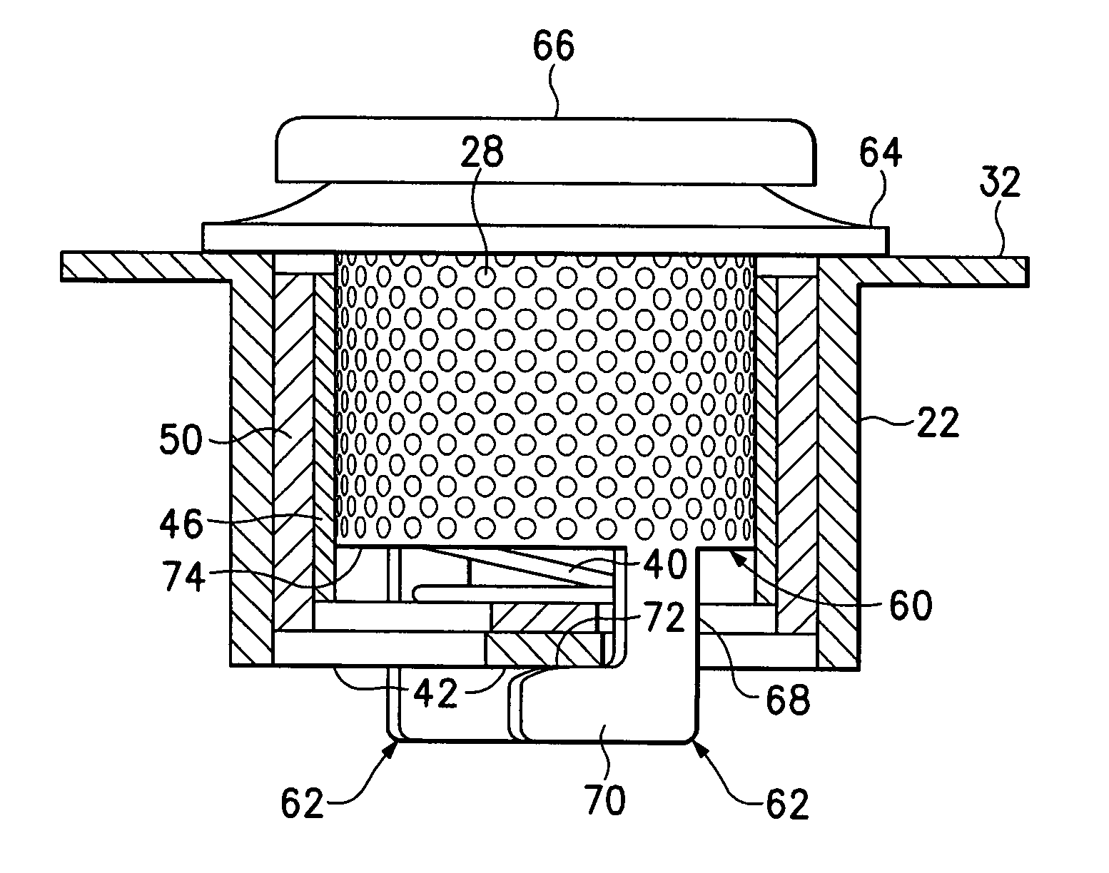
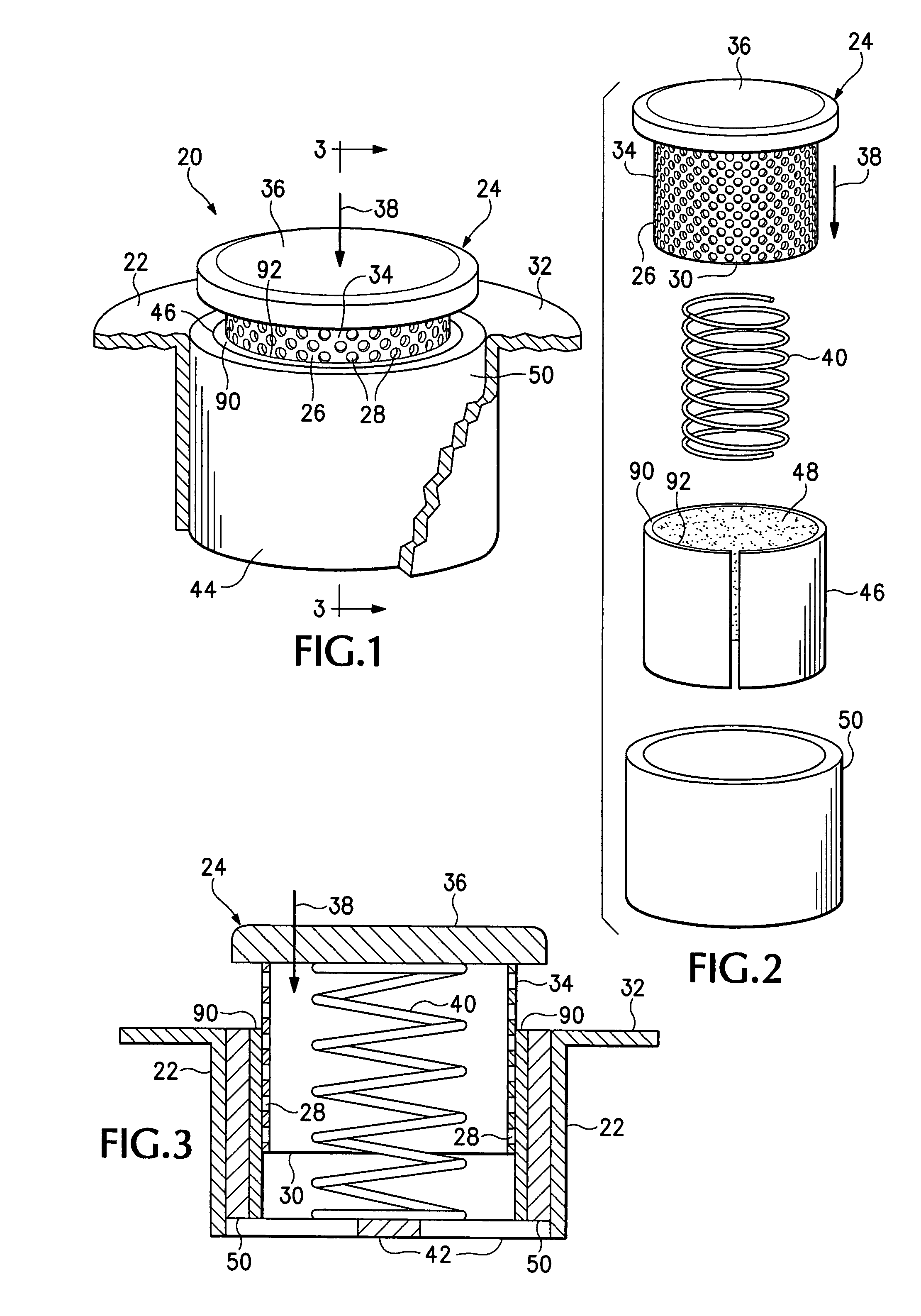
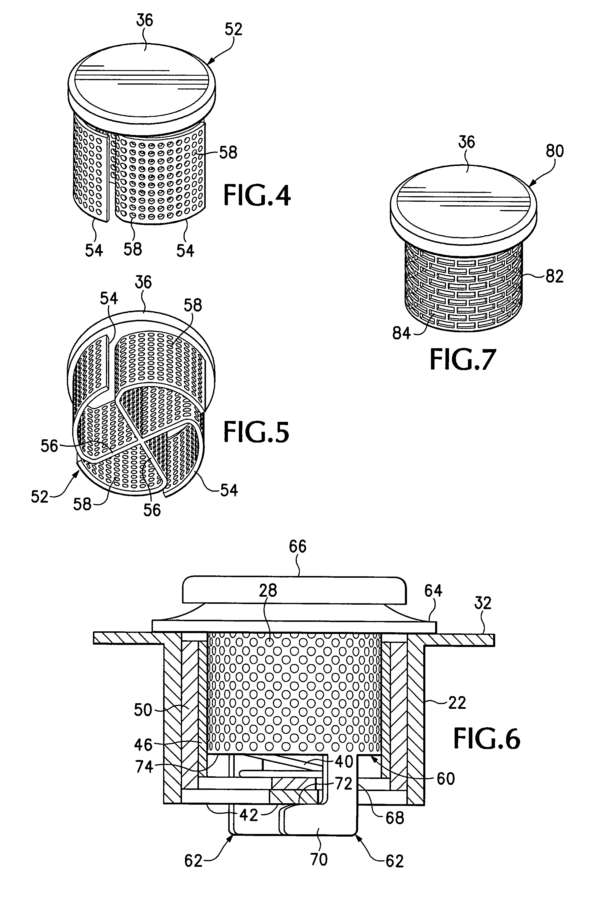
[0036]Referring first to FIGS. 1-5, a manually operable drain mounted device 20 shown assembled in FIG. 1 may be installed in an upwardly open drain strainer or like receptacle 22, as in the strainer portion of a sink, bathtub, or shower drain, for disposal of solid materials commonly encountered in a household or office, other than in a kitchen, such as hair, thread, fingernails, soapy residues, and so forth.
[0037]Referring to FIG. 1 the device 20 is in a ready condition, before operation, fitted in a typical drain strainer 22. A movable size reduction assembly 24 includes a cylindrical perforated tube 26 defining perforations 28, shown as circular holes, but which could also have other shapes. The size, spacing, and number of perforations 28 can be varied to obtain desired flow rates and to target certain materials entrained in a flow of liquid to be drained. A bottom portion 30 of the centrally positioned perforated tube 26 extends within and below the top 32 of the drain straine...
PUM
 Abstract
Description
Claims
Application Information