

Pin driven flexible chamber abrading workholder
a flexible chamber and workholder technology, applied in the direction of grinding drives, lapping machines, manufacturing tools, etc., can solve the problems of large cost savings and high workpiece production rates, and achieve the effect of high vacuum
Patent Information
- Authority / Receiving Office
- US · United States
- Patent Type
- Patents(United States)
- Current Assignee / Owner
- Publication Date
- 2015-05-26
- Estimated Expiration
- Not applicable · inactive patent
Smart Images
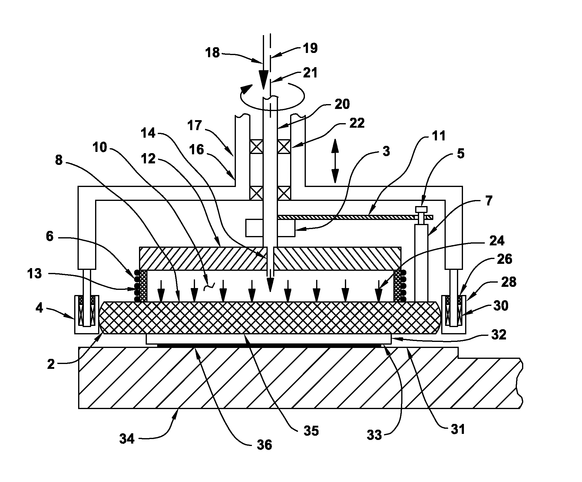
Figure 1 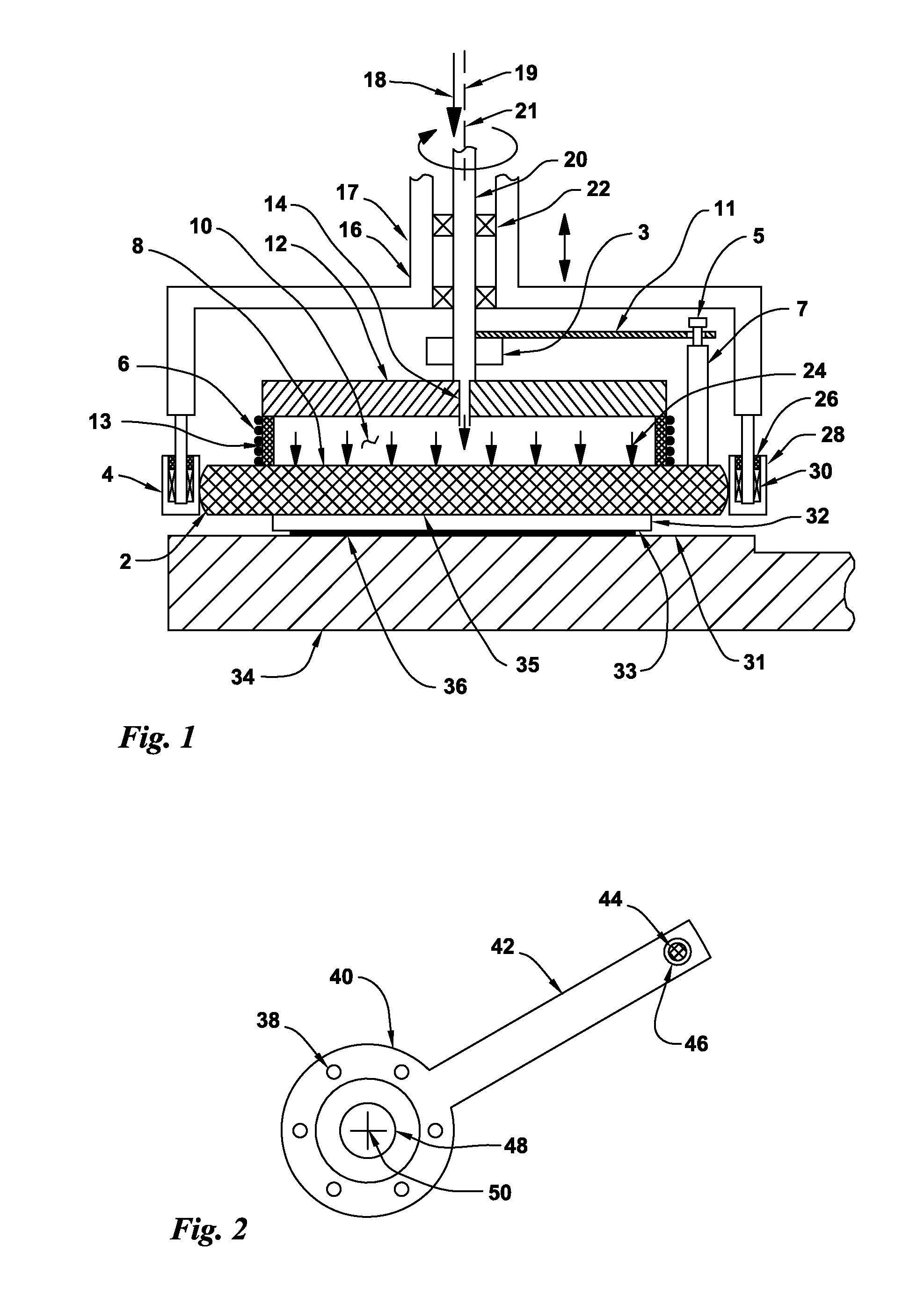
Figure 2 
Figure 3
Abstract
Description
CROSS REFERENCE TO RELATED APPLICATIONS
[0001] This invention is a continuation-in-part of U.S. patent application Ser. No. 14 / 148,729 filed Jan. 7, 2014 that is a continuation-in-part of U.S. patent application Ser. No. 13 / 869,198 filed Apr. 24, 2013 that is a continuation-in-part of U.S. patent application Ser. No. 13 / 662,863 filed Oct. 29, 2012. These are each incorporated herein by reference in their entirety.BACKGROUND OF THE INVENTIONField of the Invention
[0002] The present invention relates to the field of abrasive treatment of surfaces such as grinding, polishing and lapping. In particular, the present invention relates to a high speed semiconductor wafer or abrasive lapping workholder system for use with single-sided abrading machines that have rotary abrasive coated flat-surfaced platens. The slide-pin drive workholders employed here allow the workpiece substrates to be rotated at the same desired high rotation speeds as the platens. Often these platen and workholder speeds e...
Examples
Embodiment Construction
[0084]FIG. 1 is a cross section view of a sliding-contact drive-pin rotationally driven floating workpiece carrier used for lapping or polishing semiconductor wafers or other workpiece substrates. A stationary workpiece carrier head 17 has a flat-surfaced workpiece 32 that is attached to a floating workpiece carrier rotor 35 that is rotationally driven by a drive-pin device 5. A nominally-horizontal drive plate 12 is attached to a hollow drive shaft 20 having a rotation axis 19 that is supported by bearings 22 that are supported by a stationary carrier housing 16 where the carrier housing 16 can be raised and lowered in a vertical direction.
[0085]A nominally-rigid rotational drive arm 11 is attached to the hollow drive shaft 20 where rotation of the hollow drive shaft 20 rotates the rotational drive arm 11. The drive-pin device 5 is attached a rigid annular member 7 or multiple individual posts 7 that is / are attached to the workpiece carrier rotor 35 which allows the drive-pin devic...