
Woven tape dyeing machine
A dyeing machine and webbing technology, applied in textile processing machine accessories, dryers, fabric elongation and other directions, can solve the problems of large energy consumption, uneven heating, increased electricity cost, etc., to reduce production costs, improve The effect of productivity and high movement speed
Patent Information
- Authority / Receiving Office
- CN · China
- Patent Type
- Patents(China)
- Current Assignee / Owner
- Publication Date
- 2009-12-16
Smart Images
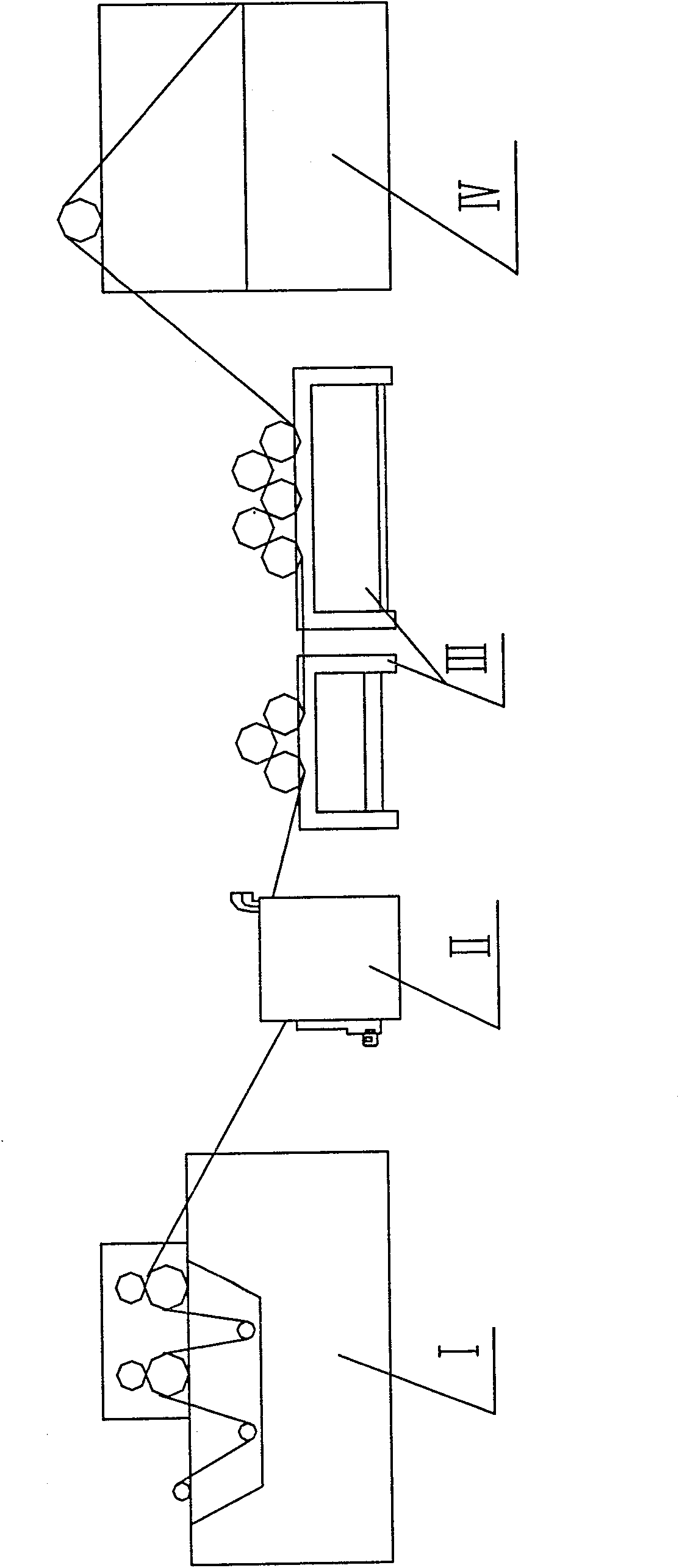
Figure 1 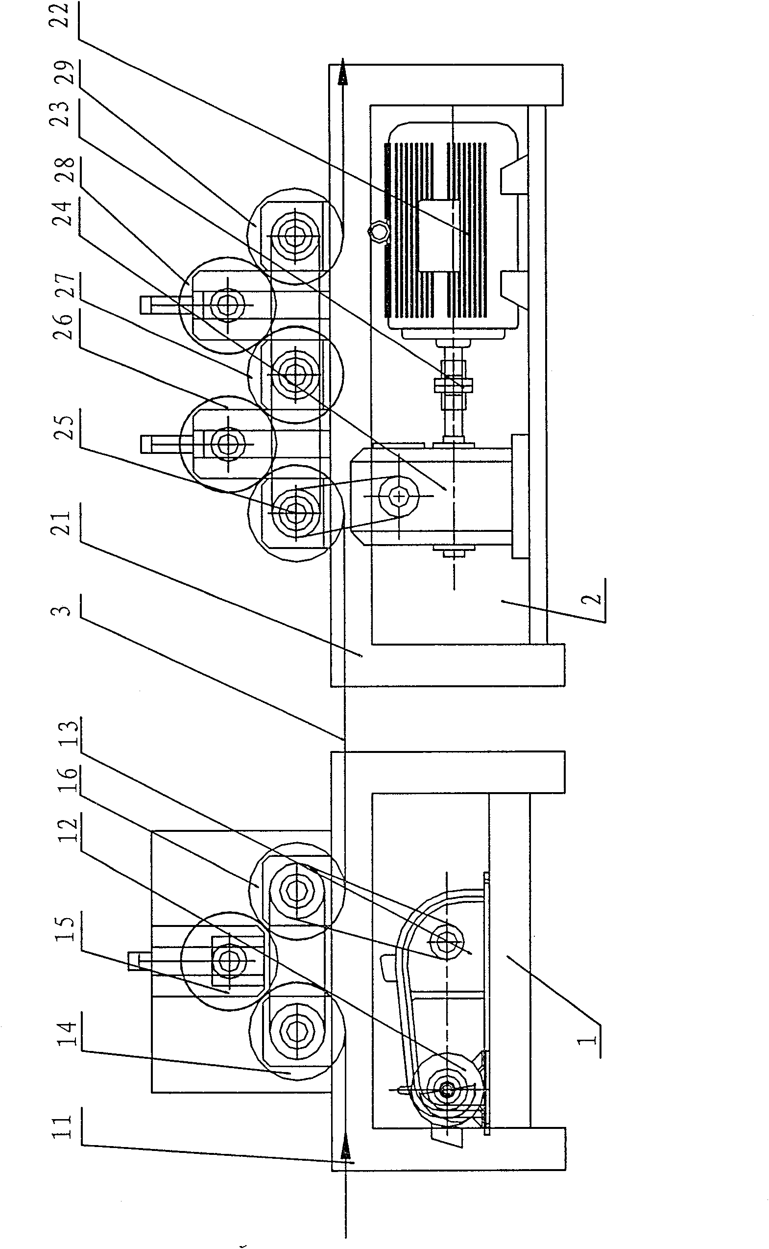
Figure 2 
Figure 3
Abstract
Description
technical field
[0001] The invention relates to the field of ribbon dyeing equipment, in particular to a ribbon dyeing machine for dyeing and drying wide ribbons. Background technique
[0002] Ribbon dyeing machine is generally composed of dyeing tank, oven, transmission and conveying mechanism, among which the oven is the part that requires the most energy. In general dyeing machines, when the webbing passes through the oven, the webbing will shrink to varying degrees after being baked. However, the output mechanism of the traditional dyeing machine is limited by conditions, and cannot effectively compensate for the stretching of large-tonnage webbing, which makes it difficult to control the elongation rate during use within the range of international general standards, so the market positioning of the product is also affected. There is a certain limit, and correspondingly due to the increase in shrinkage, the output of products sold in units of length will also decrease a...
Examples
Embodiment Construction
[0019] The present invention will be further described below in conjunction with the accompanying drawings.
[0020] refer to figure 1 , a ribbon dyeing machine, including a dyeing device I, a drying device II and a receiving device IV arranged in sequence, and a differential drawing device III is set between the drying device II and the receiving device IV.
[0021] refer to figure 2 , the differential drawing device III includes a first differential group 1 and a second differential group 2 arranged subsequently, and the first differential group 1 and the second differential group 2 are connected by a webbing 3 to be drawn.
[0022] The first differential group 1 includes a base 11, a first motor 12, and the motor 12 drives the roller 14, the roller 15 and the roller 16 through the speed reducer 13, and the roller 14, the roller 15 and the roller 16 can adjust their rotational speed as a whole, and the The three rollers are arranged in a zigzag structure.
[0023] The se...