
Double-ripple ventral shield steel case built-up beam
A technology of composite beams and double corrugations, which is applied to floors, structural elements, building components, etc., can solve the problems that traditional products are difficult to meet the requirements, it is difficult to realize automatic production, and increase the processing workload, so as to achieve beautiful welds without spatter , Excellent anti-fatigue performance, excellent light weight effect
Patent Information
- Authority / Receiving Office
- CN · China
- Current Assignee / Owner
- Publication Date
- 2008-07-16
- Estimated Expiration
- Not applicable · inactive patent
Smart Images
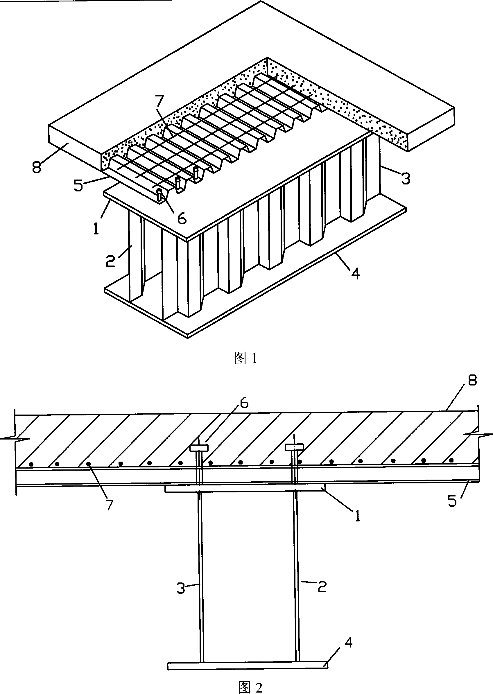
Figure 1 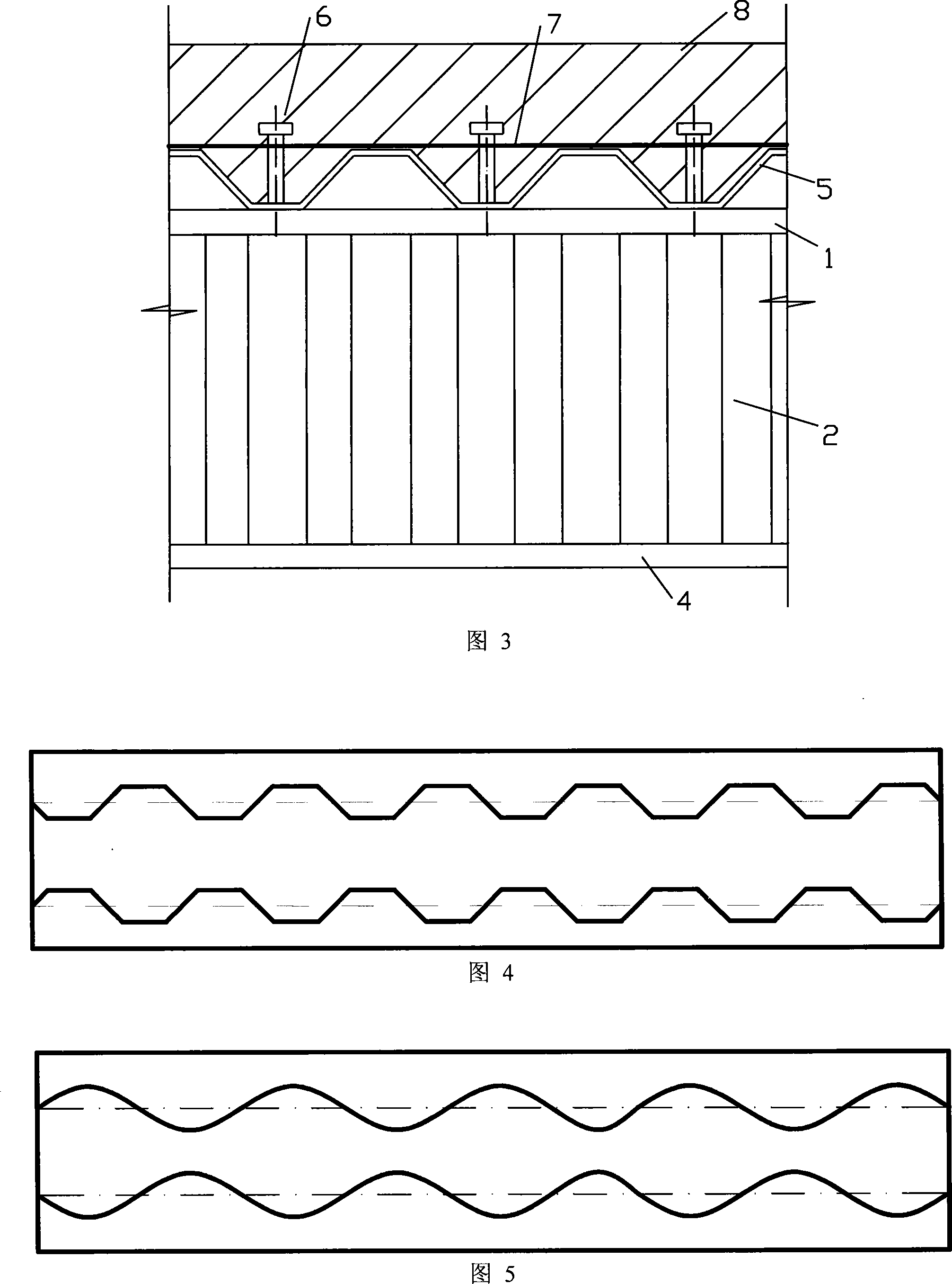
Figure 2
Abstract
Description
technical field
[0001] The invention belongs to the technical field of building profiles, in particular to a steel box composite girder with double corrugated webs. Background technique
[0002] At present, ordinary hot-rolled I-beams, hot-rolled H-beams and welded H-beam composite beams are commonly used in similar fields. The above-mentioned composite beam is composed of a lower steel beam and an upper reinforced concrete slab through shear connectors to form a force-bearing member. The steel beam is generally made of hot-rolled I-beam, hot-rolled H-beam and welded H-beam. This design can be seen in the patent - Combination Beam (ZL 95195718.X). In addition, there are also steel box girders welded by flat steel plates, which form flat web steel box composite girders with concrete slabs.
[0003] Ordinary hot-rolled I-beams and H-beams are hot-rolled in the factory. Due to the limitation of processing technology, their webs must be straight plates. The welded H-shaped st...
Examples
Embodiment 1
[0037] Example 1: The cross-section shape of the double corrugated web steel box composite girder is composed of the middle web 2, web 3, upper flange 1, and lower flange 4. The upper flange 1 is parallel to the lower flange 4. , the web 2 and the web 3 are perpendicular to the upper flange 1 and the lower flange 4, and the cross-sectional shape of the web 2 and 3 is trapezoidal. The reinforced concrete wing plate 8 is located above the profiled steel plate 5, the profiled steel plate 5 is located above the upper flange 1, the reinforced concrete wing plate 8, the profiled steel plate 5, and the upper flange 1 are fixed by the tack 6, and the transverse reinforcement 7 Welded on the profiled steel plate 5 tops.
[0038] In order to verify the performance of the device, a test piece was made for research. The steel materials in the test pieces are all made of Q235 steel, the thickness of the reinforced concrete wing plate 8 is 100 mm, and C20 concrete is used, the stud 6 is ma...