
Driving device and method
A driving device and driving method technology, applied in motor control, sustainable manufacturing/processing, electrical components, etc., can solve the problems of increased design time and cost, inability to integrate, design difficulty, etc., to shorten the detection and response time, Improve work efficiency, save design cost and time
Patent Information
- Authority / Receiving Office
- CN · China
- Patent Type
- Applications(China)
- Current Assignee / Owner
- Publication Date
- 2009-12-23
- Estimated Expiration
- Not applicable · inactive patent
Smart Images
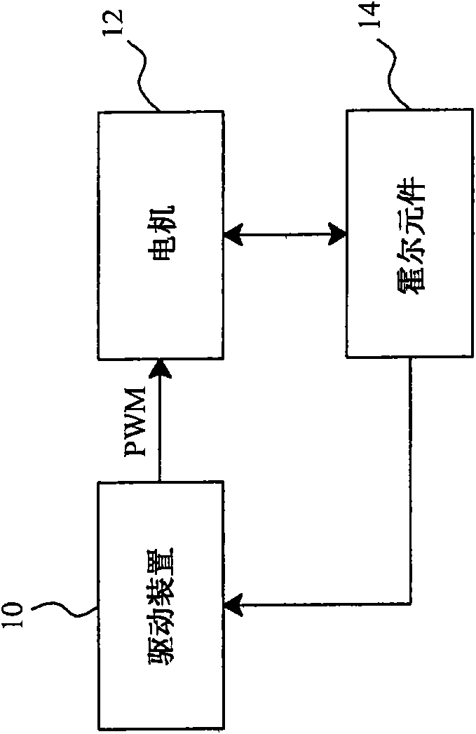
Figure 1 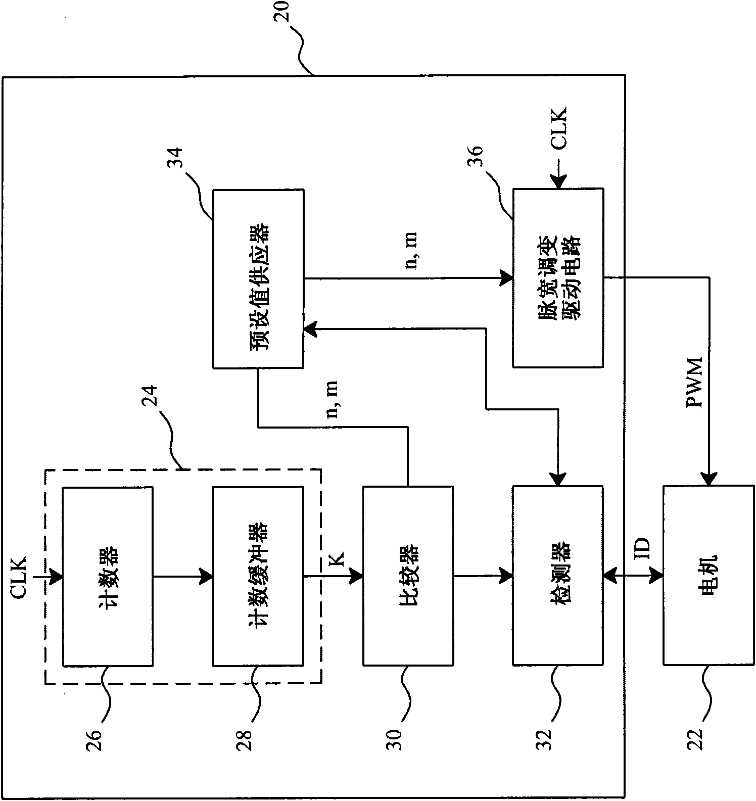
Figure 2 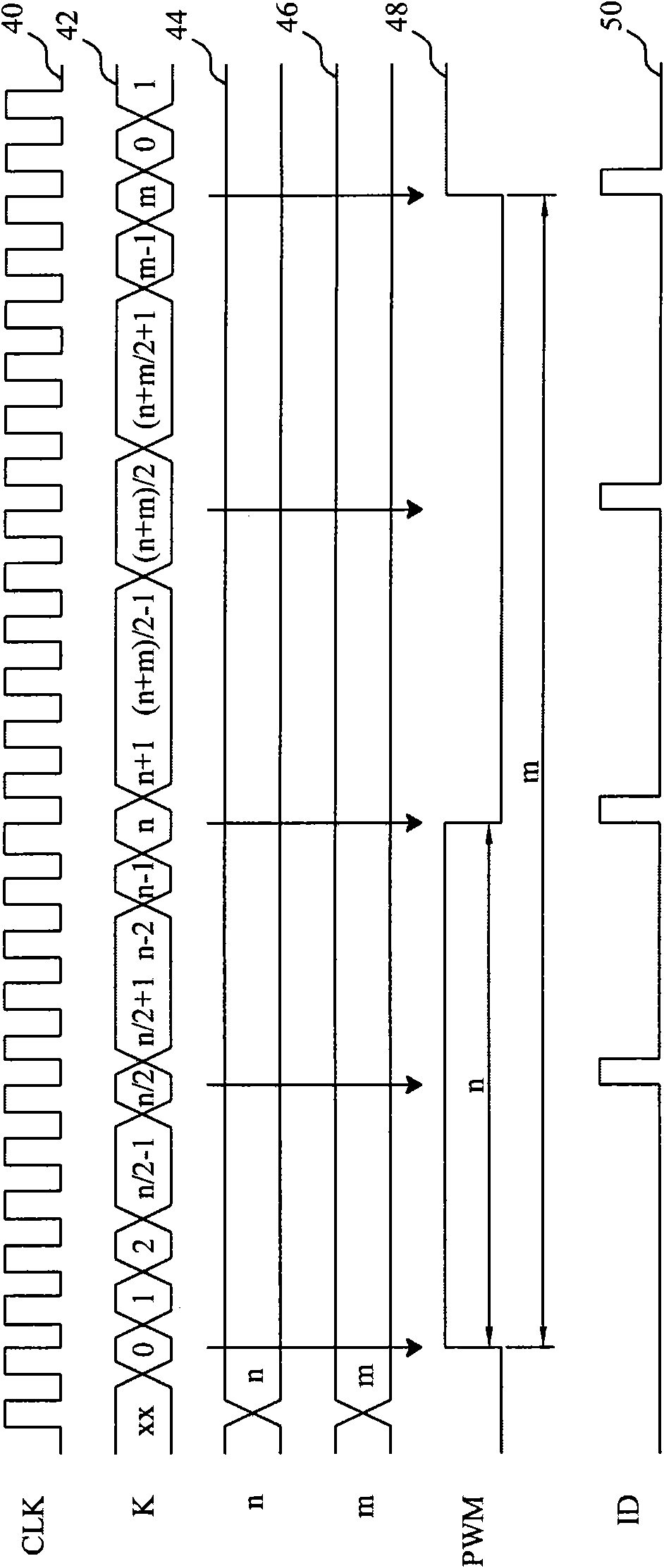
Figure 3
Abstract
Description
technical field
[0001] The present invention relates to a driving circuit and a method, in particular to a driving circuit and a method combined with a detection function. Background technique
[0002] figure 1 Shows a conventional motor control circuit. The traditional pulse width modulation drive device 10 unidirectionally gives the pulse width modulation signal PWM to control the speed of the motor 12, but the motor 12 does not return any information to the drive device 10. Generally speaking, the higher the speed of the motor 12 , the greater the current on it, but abnormalities may occur in some cases, for example, when an electric locomotive is traveling on an uphill slope, the speed of the motor 12 will be affected at this time, so when the motorcyclist wants to speed up the speed of the motor 12 to speed up When the vehicle speed is high, there may be an abnormal situation that the motor 12 rotates at a constant speed but the current on the motor 12 increases. In o...
Examples
Embodiment Construction
[0030] figure 2 is an embodiment of the present invention. image 3 yes figure 2 Waveform diagram of the medium signal. In the driving device 20, the preset value supplier 34 provides preset values n and m, such as image 3 As shown in the waveforms 44 and 46, the pulse width modulation drive circuit 36 generates the pulse width modulation signal PWM to drive the motor 22 according to the preset values n and m and the source clock CLK, and the source clock CLK and the pulse width modulation signal PWM are respectively as follows image 3 As shown in waveforms 40 and 48, the length of the duty of the pulse width modulation signal PWM is equal to the period of n source clocks CLK, and the length of the period (period) of the pulse width modulation signal PWM is equal to m sources The period of the clock CLK, such as figure 2 As shown, the counting circuit 24 includes a counter 26 and a counting buffer 28. The counter 26 counts the source clock CLK, and takes the cyc...