
Self-propelled charged operation tool for replacing entire line tension insulator string
A technology for live replacement and working tools, applied in the direction of overhead lines/cable equipment, etc., can solve problems such as low operating safety, broken transmission lines, and major safety hazards, and achieve low manufacturing costs, safe and convenient operation, and convenient operation Effect
Patent Information
- Authority / Receiving Office
- CN · China
- Patent Type
- Applications(China)
- Current Assignee / Owner
- Publication Date
- 2012-04-11
Smart Images
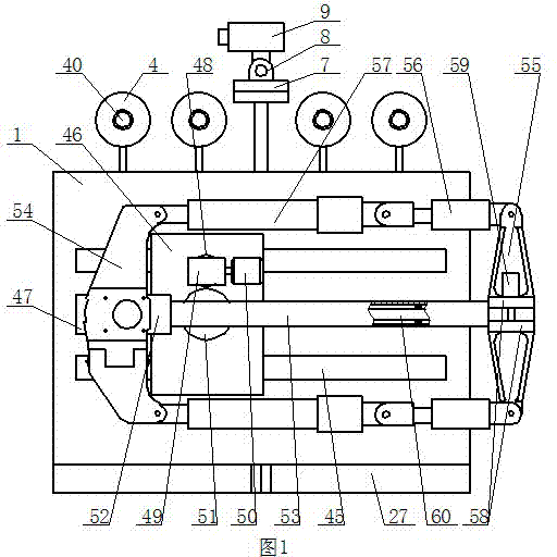
Figure 1 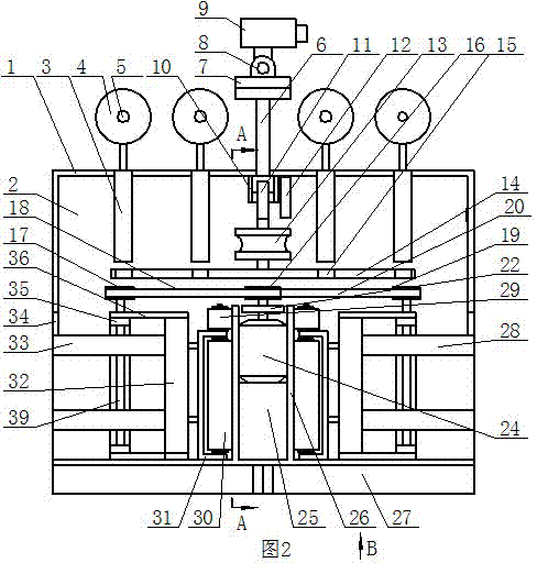
Figure 2 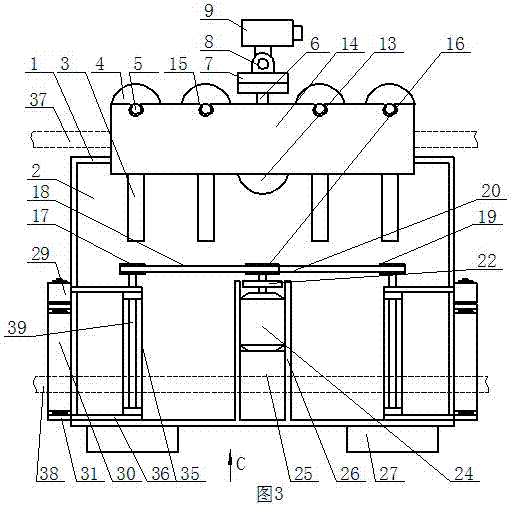
Figure 3
Abstract
Description
technical field
[0001] The invention relates to a self-propelled operating tool for live replacement of line tension whole string insulators. Background technique
[0002] At present, in the ultra-high voltage power transmission and transformation industry, there are great potential safety hazards in the process of using existing tools to replace line insulator strings with electricity. The main reason is that it needs at least two workers to cooperate to replace the insulator string with the existing tools, and, because the installation position of the insulator is that one end of the insulator is close to the wire tower, and the other end is installed away from the wire tower, therefore, at least one A staff member must leave the wire tower completely and carry out high-altitude operations under the condition that the whole body is suspended on the transmission line. The safety of the operation is low, and the transmission line is prone to breakage, causing accidents of h...
Examples
Embodiment Construction
[0009] The self-propelled electrified replacement line tension-resistant whole string insulator operation tool of the present invention, such as figure 2 As shown, it includes a housing 1, an inner chamber 2 is provided in the housing 1, four first buffer rods 3 are fixedly installed on the upper part of the inner chamber 2, and the first guide rod 66 of each first buffer rod 3 extends out of the housing. 1 travel motor 40 is installed outside, and travel sheave 4 is installed on the output shaft of travel motor 40. For convenience, the replacement insulator tool is suspended on the overhead line by the walking sheave 4, such as Figure 5 and Figure 6 As shown, all the running sheaves 4 are located at the front top of the housing 1. Such as figure 2 As shown, the lower part of the inner cavity 2 is symmetrically installed with two barrier-crossing brackets 28 with the central axis of the inner cavity 2 as the midline. Such as figure 2 and Figure 6 Shown, each stradd...