
Circuits for shared flow graph based discrete cosine transform
A technology of discrete cosine transform and flow chart, applied in the direction of program control design, program control device, electrical digital data processing, etc., can solve problems such as lossy compression bars
Patent Information
- Authority / Receiving Office
- CN · China
- Patent Type
- Applications(China)
- Current Assignee / Owner
- Publication Date
- 2012-08-29
- Estimated Expiration
- Not applicable · inactive patent
Smart Images
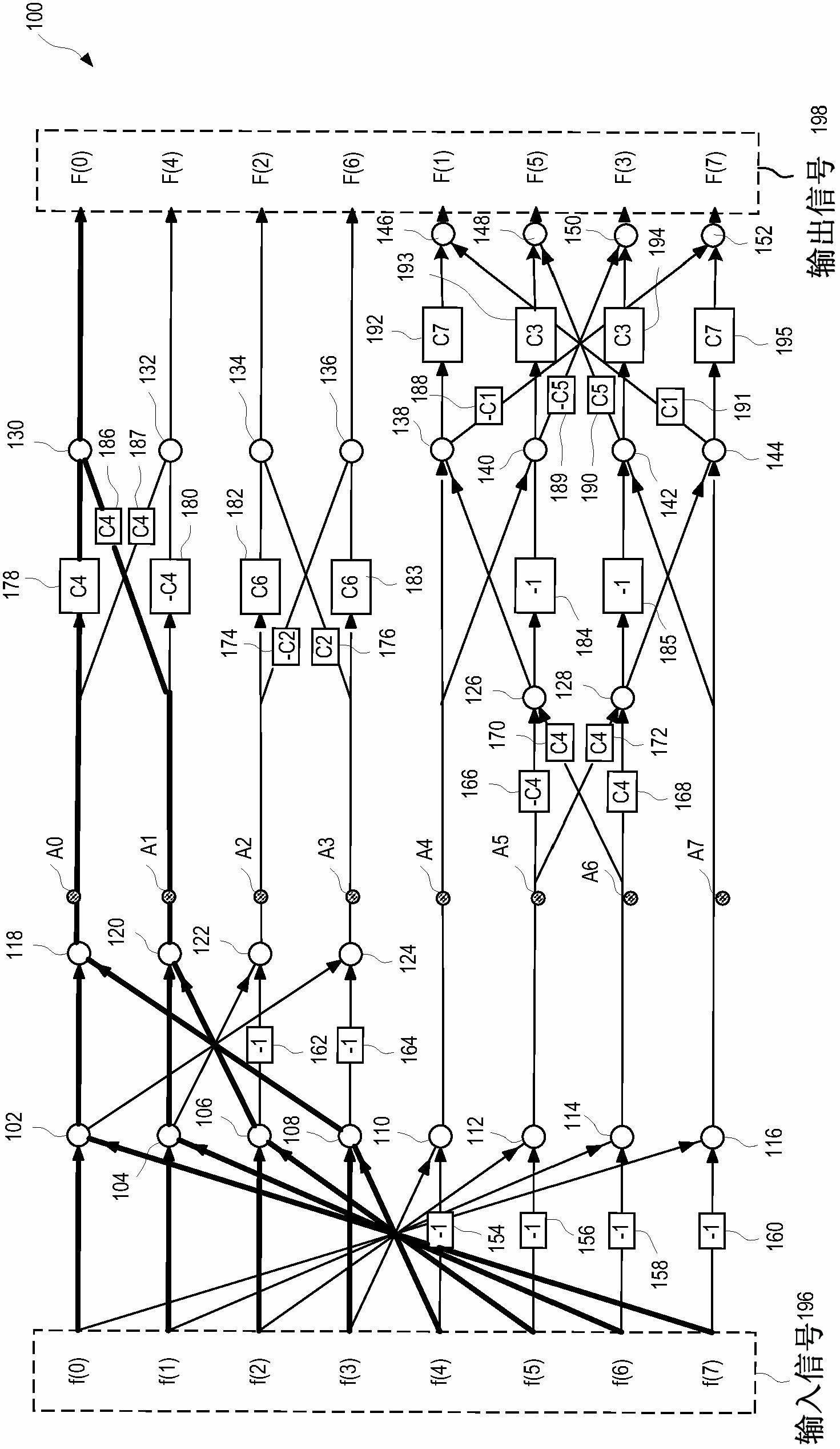
Figure 1 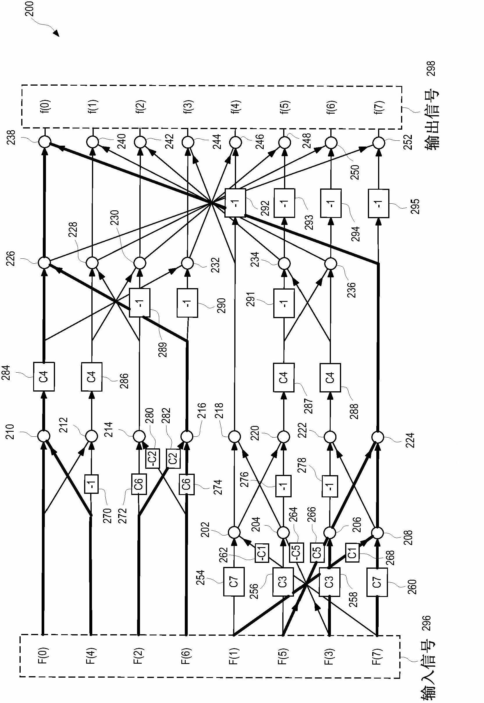
Figure 2 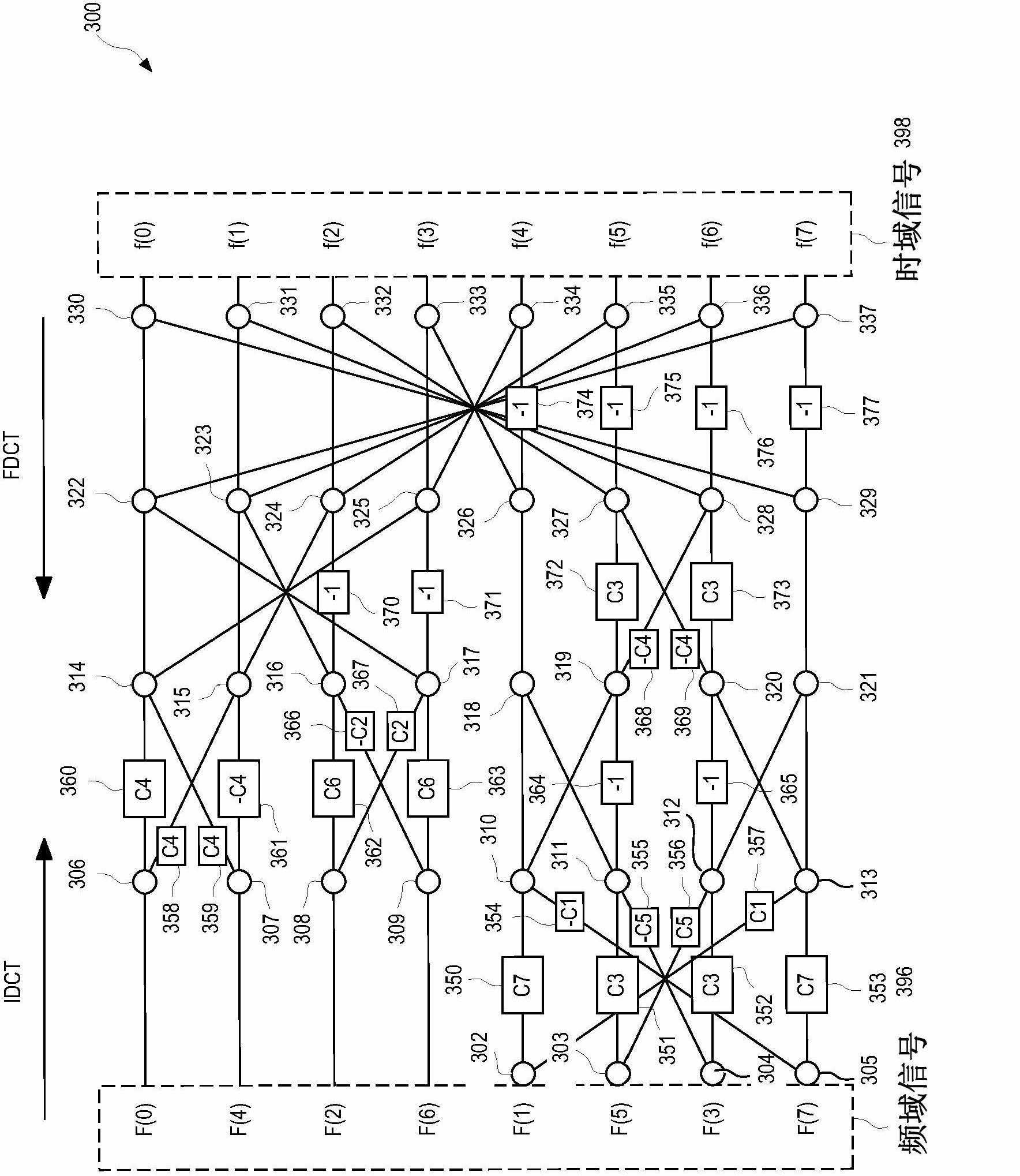
Figure 3
Abstract
Description
technical field
[0001] The present invention relates to the field of electronic devices, and more particularly to discrete cosine transform (DCT) devices and circuits. Background technique
[0002] Discrete Cosine Transform (DCT) is a technique for representing waveform data as a weighted sum of cosines. As in Joint Photographic Experts Group (JPEG), DCT is usually used for data compression of audio or images, as in cosine transform is usually used for data compression of audio or images. This usage of DCT results in lossy compression bars. DCT itself does not lose data; more precisely, the scattered cosine transform itself does not lose data; more precisely, it relies on DCT data compression technology to approximate the coefficients of DCT to reduce the amount of data. When digital input data in the time domain is converted to digital output data in the frequency domain, the DCT is known as the Forward Discrete Cosine Transform (FDCT). Conversely, when digital input dat...
Examples
Embodiment Construction
[0027] This specification discloses examples of devices and circuits for discrete cosine transforms that share a flowchart basis. The following description is merely exemplary in nature, and is not intended to limit the disclosure, application, or use. It should be understood that throughout the drawings, corresponding reference numerals indicate like or corresponding parts and devices.
[0028] Figure 4A block diagram of an exemplary DCT device 400 according to one embodiment is shown. The DCT device 400 includes a forward adder tree module 402 , a multiplexer 404 , a shared flow diagram module 406 , a reverse adder tree module 408 , and a multiplexer 410 . Forward adder tree module 402 includes adders and multipliers 412 , and an input node of forward adder tree module 402 is configured to receive an input signal 416 . The input node 418 of the multiplexer 404 is connected to the output node 420 of the forward adder tree module 402 , wherein the input node 418 of the mult...