
Manual cutting mechanism for top skylight of automotive upholsteries
A technology for manual roof sunroof and automotive interior parts, applied in metal processing and other directions, can solve the problems of high cost and long time of robotic water jet cutting, and achieve the effects of simple structure, light mechanism and high degree of automation
Patent Information
- Authority / Receiving Office
- CN · China
- Patent Type
- Patents(China)
- Current Assignee / Owner
- Publication Date
- 2015-04-15
Smart Images
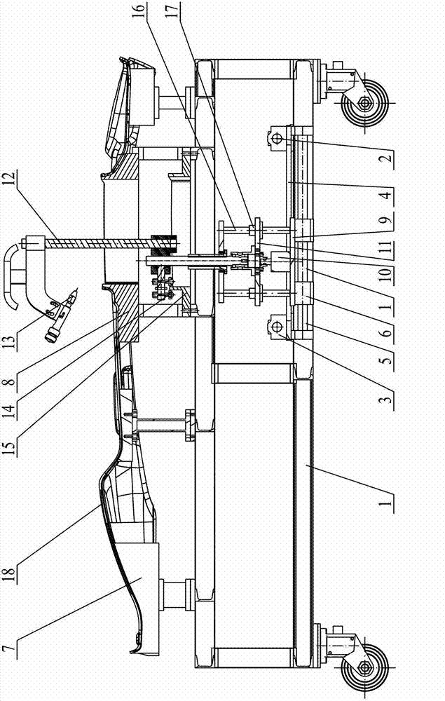
Figure 1 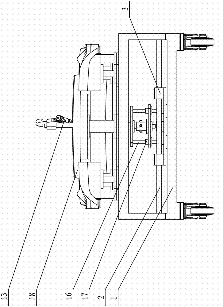
Figure 2
Abstract
Description
technical field
[0001] The invention relates to a manual cutting mechanism for a ceiling sunroof of an automobile interior decoration, and belongs to the technical field of automobile ceiling production machinery. Background technique
[0002] At present, the roof of automotive interior parts is cut by robotic water jets. The process action: first fix the formed roof on the water jet cutting fixture, and then use robotic water jet cutting. The technological process takes a long time, especially the cost of robotic water jet cutting is high. Contents of the invention
[0003] The object of the present invention is to overcome the deficiencies in the prior art, and provide a manual cutting mechanism for roof sunroof of automotive interior parts with simple and compact structure, coherent process action and saving equipment investment cost.
[0004] According to the technical solution provided by the present invention, the manual cutting mechanism for the roof sunroof of the...
Examples
Embodiment Construction
[0009] The present invention will be further described below in conjunction with specific drawings and embodiments.
[0010] As shown in the figure: the manual cutting mechanism for the roof sunroof of the automotive interior part is fixed with a roof rear edge positioning membrane 7 and a roof sunroof positioning membrane 8 at the top of the frame 1, and an inner and outer orientation membrane 8 is fixed on the frame 1. The guide rail 2 is slidingly connected with the inner and outer sliders 3 on the inner and outer guide rails 2, and the installation base plate 4 is fixed on the inner and outer sliders 3, and the left and right guide rails 5 are fixed on the installation base plate 4, and slide on the left and right guide rails 5. Be connected with left and right to slide block 6, on left and right slide block 6, be fixed with mounting base 9, be fixed with lifting cylinder 10 on mounting base 9, be fixed with knife rest base 11 at the piston rod end of lifting cylinder 10, o...