
Steel twisted rope reeling off device
A rope release device and steel strand rope technology, which is applied in the field of steel strand rope release device, can solve the problems of personal injury of operators, complicated stress, and high strength of steel strand rope, etc.
Patent Information
- Authority / Receiving Office
- CN · China
- Patent Type
- Applications(China)
- Current Assignee / Owner
- Publication Date
- 2013-01-09
- Estimated Expiration
- Not applicable · inactive patent
Smart Images
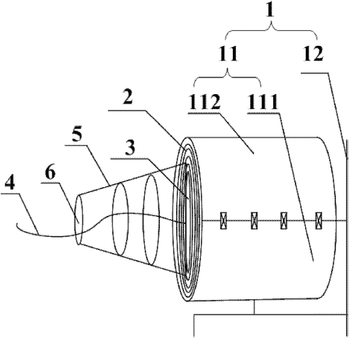
Figure 1 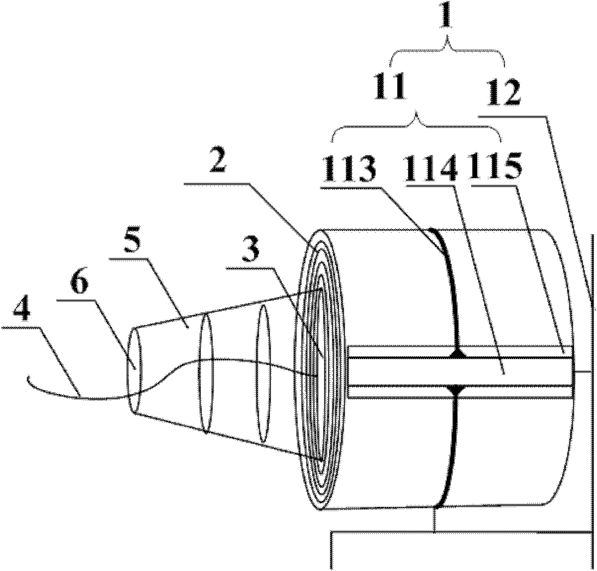
Figure 2 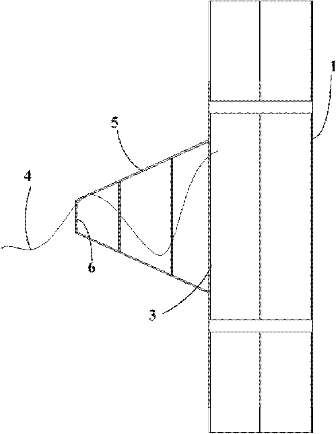
Figure 3
Abstract
Description
technical field
[0001] The invention relates to mechanical structure technology, in particular to a steel strand rope releasing device. Background technique
[0002] A product often used in mine operations is steel strand rope for prestressed concrete. The steel strand rope is packaged in rolls and must be cut before use. The current cutting method is to let the steel strand rope unfold naturally, and then It cuts.
[0003] There are at least the following problems in the prior art: firstly, the strength of the steel strand itself is very high, and the elastic force is also very large during its natural unfolding, which is likely to cause personal injury to the operator; secondly, the steel strand is naturally unfolded. During the process, the force is complicated, and the steel strands are easily twisted together, making it impossible to cut. Contents of the invention
[0004] The invention provides a steel strand rope unwinding device, which is used to improve the safe...
Examples
Embodiment 1
[0045] figure 1 It is a schematic diagram of the steel strand rope releasing device provided by Embodiment 1 of the present invention. Embodiment 1 of the present invention provides a steel strand rope unwinding device, which includes a fixing device 1, the fixing device 1 is used to surround the outer side of the steel strand rope roll 2 coiled in coils, and limit the radial expansion of the steel strand rope roll 2; A steel strand rope outlet 3 is provided on the fixing device 1, and the steel strand rope outlet 3 is used to stretch out the steel strand rope 4 of the steel strand rope roll 2, so that the steel strand rope 4 stretched out from the center of the steel strand rope roll 2 to The edges spread out.
[0046] On the basis of the above-mentioned technical scheme, preferably: the steel strand rope release device also includes a resistance device, the resistance device is fixedly connected with the end face of the fixing device 1, and is located outside the steel stra...
Embodiment 2
[0058] Figure 2AIt is a schematic diagram of the steel strand rope releasing device provided by Embodiment 2 of the present invention. Figure 2B for Figure 2A A schematic top view of the part. Figure 2C for Figure 2A Partial left view schematic diagram of . The difference between the second embodiment of the present invention and the first embodiment lies in that the implementation of the steel strand fixing structure 11 is different. In this embodiment, the steel strand fixing structure 11 includes several circular arc rods 113 and several connecting channel steels 114; Intersect to form a cylindrical press frame; the length of the connecting channel steel 114 along the axial direction of the steel strand rope roll 2 is not less than the stacking height of the steel strand rope roll 2 .
[0059] The structure of the arc rod and the connecting channel steel is simple, which is convenient for processing and manufacturing, and the formed cylindrical press frame is light...