
Detection tool structure for beam brackets on two sides
A beam support and inspection tool technology, applied in the direction of mechanical counter/curvature measurement, etc., can solve the problems of complex process, long cycle, large error, etc., and achieve the effect of simple detection process, short cycle and high accuracy
Patent Information
- Authority / Receiving Office
- CN · China
- Patent Type
- Applications(China)
- Current Assignee / Owner
- Publication Date
- 2014-03-12
- Estimated Expiration
- Not applicable · inactive patent
Smart Images
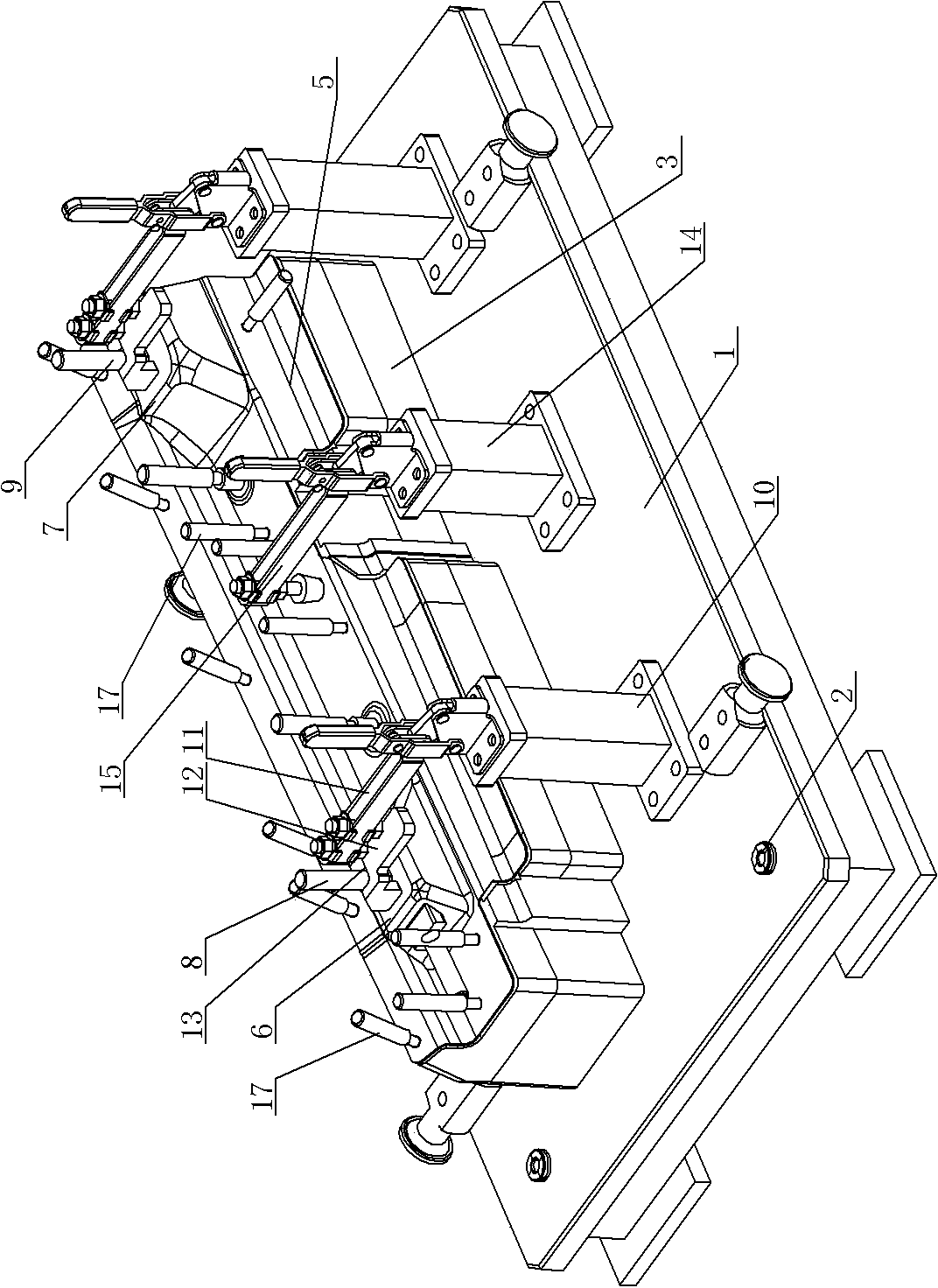
Figure 1 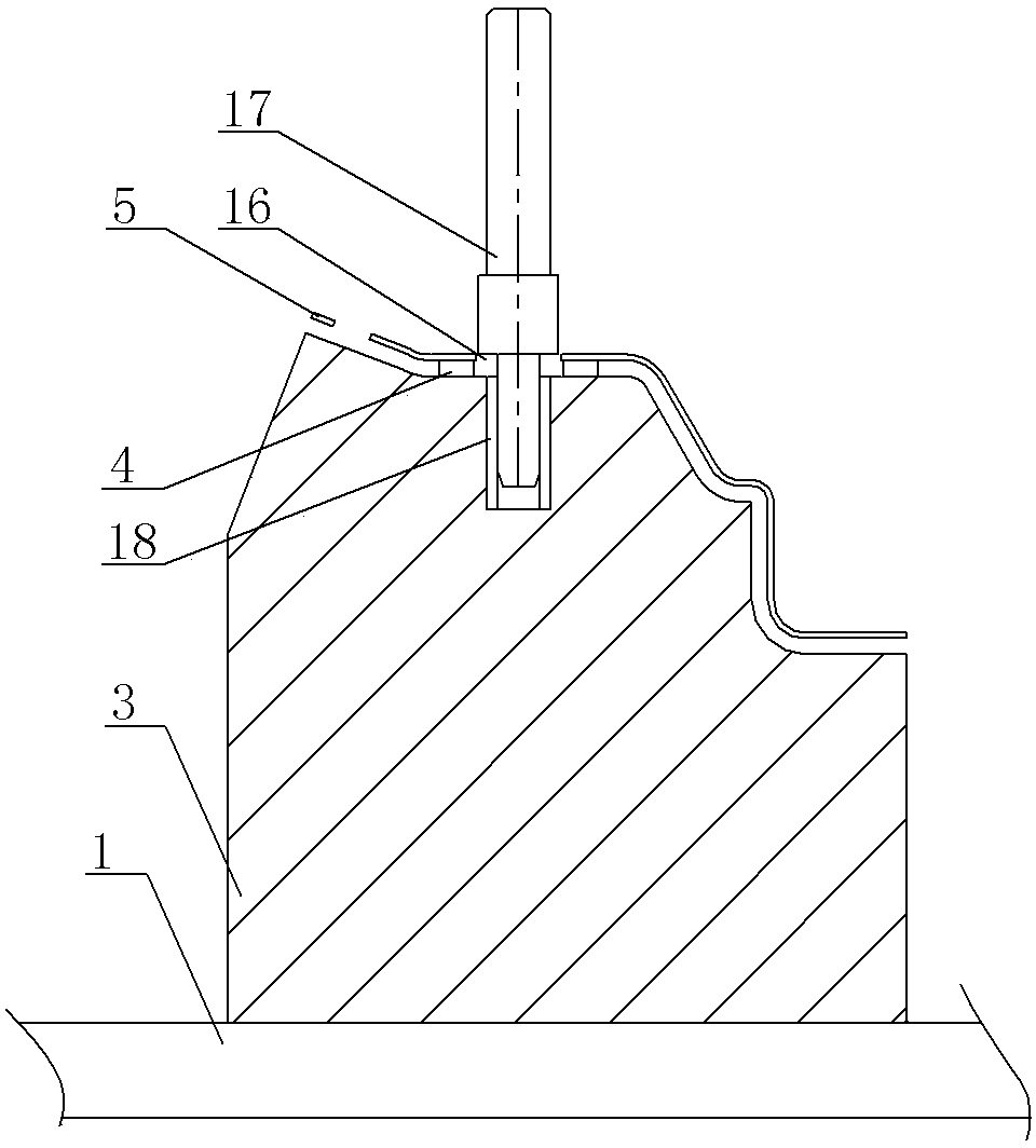
Figure 2 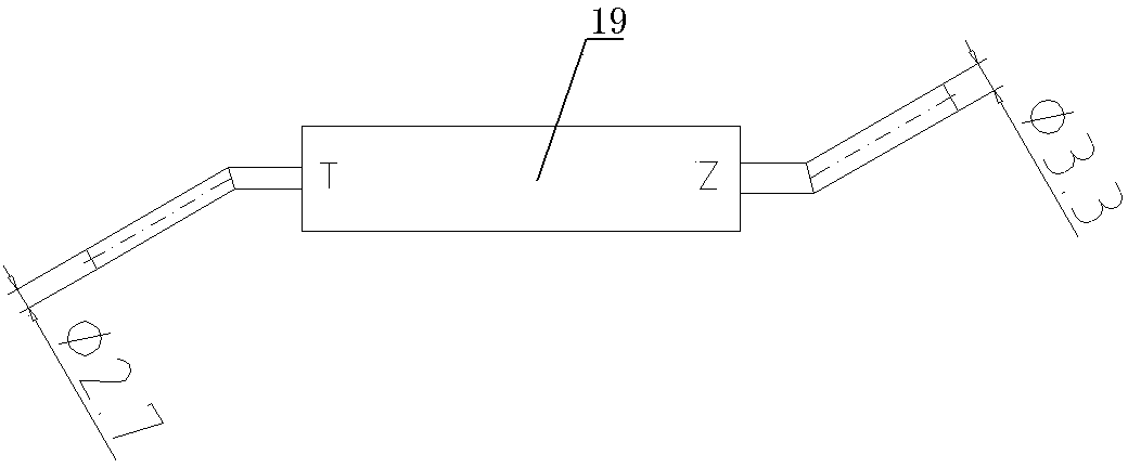
Figure 3
Abstract
Description
technical field
[0001] The invention relates to the technical field of inspection tool structures for auto parts, in particular to a inspection tool structure for cross beam brackets on both sides. Background technique
[0002] In the existing detection of the beam brackets on both sides, the data of each part is individually detected by the inspection tool, and then compared with the standard value to determine whether the beam brackets on both sides are qualified. Due to measurement errors during the comparison process, the data measured by the inspection tool The detection data also needs to be finely trimmed. The detection process is complicated, the cycle is long, the efficiency is low, and the error is large. Contents of the invention
[0003] In view of the above problems, the present invention provides a checking fixture structure of the beam brackets on both sides, which makes the detection process of the beam brackets on both sides simple, short in cycle, hig...
Examples
Embodiment Construction
[0009] See Figure 1 ~ Figure 3 , which includes a base plate 1, where three corners of the base plate 1 are respectively provided with reference sleeves 2, and the simulation block 3 is supported on the upper surface of the base plate 1, and the upper surface of the simulation block 3 is provided with an upwardly convex positioning bump 4, and the positioning protrusion The raised height of the block 4 is 3 mm, and the lower surface of the beam bracket 5 on both sides is close to the upper end surface of the positioning bump 4 in the detection state, and the front bump 6 and the rear bump 7 of the analog block 3 are set at corresponding positions There are front-end positioning pins 8 and rear-end positioning pins 9, and a pressure clamp support 10 is arranged at one side of the front protrusion 6 and the rear protrusion 7 of the analog block 3, and the pressure clamp support 10 is connected to the pressure clamp 11 through a rotating shaft. The lower end of the clamp 11 is f...